[wpdatatable id=5]
Installation and Maintenance
test service nolan
Resources
test service nolan
[wpdatatable id=5]
test service nolan
Take your engineering career to the next level with expert-led, case-based training that transforms 10-plus years of field experience into a structured, self-paced learning path.
Created for engineers who are on the subject matter expert (SME) track, this course delivers practical tools and in-depth knowledge aligned with the ASME B31.3 standard. This self-paced course includes 10 advanced modules, covering topics from pipe wall thickness to brittle fracture.
Limited-Time Special : Get the full 10-module course for $1,995. Price increases to $2,500 on August 31, 2025.
Enroll now and earn 15 PE/PDH credits along with a certificate jointly issued by ASME and Piping Technology.
Prefer to focus on one topic? You can also purchase individual modules for $500–$650 each and earn 1 or 2 PE/PDH credits per module.
Individual modules come with a PE/PDH certificate of completion from Piping Technology & Products. Only the full course includes the joint ASME and PTP certificate.
Yes, the ASME B31.3 SME course is delivered entirely online. Course participants can begin at any time and progress through the material at their own pace.
No, the course is not offered in a traditional classroom format. All instruction is provided through pre-recorded video modules, which can be accessed from any location with an internet connection.
The course includes 10 pre-recorded modules totaling approximately 13 hours and 30 minutes of video content. This estimate reflects the core instructional videos only and does not include the time needed for exams or introductory content. As the course is self-paced, participants may take as much time as needed to complete it. Modules can be purchased separately and vary in time from 45 min to two hours per module.
There is no time limit for completion. Course participants may progress through the modules on their own schedule.
All exams are conducted online through the course platform:
While there are no live sessions, participants can submit clarification questions or content-related inquiries directly to education@pipingtech.com at any time. We pride ourselves in answering questions within one business day.
Yes, the course is open to international participants, and a digital certificate is issued upon successful completion of the course and final exam.
The limited-time special price for the full course is $1,995 per participant, available through August 31st, 2025.
This includes:
Group discounts are available for teams or organizations enrolling multiple participants. Email education@pipingtech.com for information on group pricing.

Learn how to calculate pipe wall thickness using ASME B31.3 to keep piping safe and reliable. This course simplifies key concepts so you can design pipes that handle pressure and avoid failures. Upgrade your skills to build stronger, safer piping systems.
Credit: One(1) PE/PDH Credits
Understanding design pressure and temperature is crucial for building safe piping systems. This course explains how to determine these factors using ASME B31.3 guidelines, helping you create pipes that can handle real-world conditions. By learning these concepts, you’ll enhance your ability to design reliable and efficient piping systems.
Credit: One(1) PE/PDH Credits

Learn how to analyze pipe stress using ASME B31.3 guidelines to ensure safe and efficient piping systems. This module teaches you to identify and address stress points, preventing failures and extending the lifespan of your designs. Enhance your skills to build more reliable and resilient piping infrastructures.
Credit: One(1) PE/PDH Credits
Understanding pipe bends, mitered bends, and branch connections is essential for designing safe and efficient piping systems. This module simplifies these concepts, teaching you how to apply ASME B31.3 guidelines to ensure proper flow and structural integrity. By enrolling, you’ll enhance your ability to create reliable piping layouts that meet industry standards.
Credit: One(1) PE/PDH Credits

Learn to design safe and reliable hydrogen piping systems by addressing embrittlement, material selection, and code compliance. This course covers ASME B31.3 vs. B31.12, hydrogen failure risks, and API 941 for high-temperature attack. Gain the expertise to design, review, and maintain hydrogen piping that meets industry standards.
Credit: One(1) PE/PHD Credits
Learn how to ensure strong, reliable pipe supports by applying ASME B31.3 guidelines. This course covers stress analysis, clamp design, and thermal effects, helping you prevent failures in high-temperature systems. Master key support techniques, including FEA and spring hanger selection, to optimize safety and efficiency.
Credit: One(1) PE/PDH Credits

Learn how to select and design flanges for high-temperature applications using advanced ASME guidelines. This module covers flange geometries, material selection, and the impact of thermal conductivity on performance. Through case studies, you’ll master flange class selection, bolt torque calculations, and compliance with key regulations.
Credit: Two(2) PE/PHD Credits
Understanding how to manage vibration is essential for safe and efficient piping systems. Learn how to analyze and prevent piping vibration issues using advanced modeling and FFT analysis. This module covers vibration calculations, pulsation dampener sizing, and ASME B31.3 stress adjustments. Gain hands-on skills to identify root causes and ensure safe, efficient piping systems.
Credit: Two(2) PE/PDH Credits
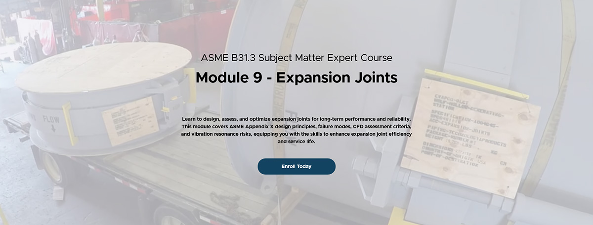
Learn how to design and optimize expansion joints to prevent failures and improve system reliability. This module covers ASME Appendix X guidelines, failure analysis, and the impact of flow and vibration on performance. Gain practical skills to enhance expansion joint longevity and ensure safe, efficient piping systems.
Credit: Two(2) PE/PDH Credits
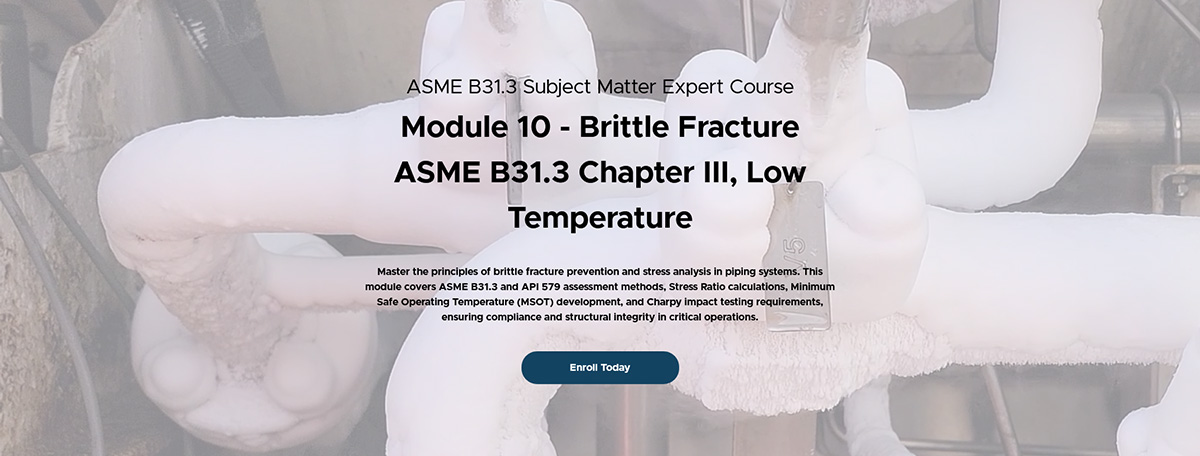
Learn how to prevent brittle fracture in piping systems by understanding stress ratios, temperature limits, and material performance. This module covers ASME B31.3 assessments, API 579 CET calculations, and Charpy impact testing. Gain practical skills in fracture risk mitigation to design safer, more reliable piping for extreme conditions.
Credit: One(1) PE/PDH Credits
Expansion Joint Application and Design Course covers how to provide flexibility in the piping system by employing expansion joints to accommodate thermal expansion and contraction of sections of pipes or ducts. It discusses the parameters and conditions specified by the piping system designer and how to design an expansion joint as a cost-effective component of the piping system.
Credit: Eight(8) PE/PHD Credits
Piping Design and Analysis Influence on Pipe Support Selection and Design is an overview on piping design and analysis, including factors that effect overall configuration, piping layout, the total system, as well as an introductory into pipe stress analysis (flexibility concerns and other design considerations); and how all those factors ultimately influence pipe support and pipe hanger design.
Credit: Eight(8) PE/PHD Credits
Expansion Joint Application and Design Course covers how to provide flexibility in the piping system
Piping Design and Analysis Influence on Pipe Support Selection and Design is an overview on piping design and analysis, including factors that effect overall configuration, piping layout, the total system, as well as an introductory into pipe stress analysis
Credit: Sixteen(16) PE/PHD Credits
test service nolan
Check out our YouTube Channel for all our videos.
test service nolan
test service nolan
This Unit Converter converts between units of Energy, Angle, Area, Conductivity, Density, Length, Mass, Volume and more.
If for some reason you do not see the Submit Button please click the Submit button i.e. the transparent box in the right bottom of the Unit Converter.
[jkluc]
test service nolan
The following are schedule sheets for PT&P constant load hangers, variable load hangers, and rod hangers. Our customers can use these different CAD forms to specify all the details of their rod assemblies.
ptp-vendor-dxf.zip : Constant Load Hanger, Variable Load Hanger and Rod Hanger Assembly worksheets in DXF format. (507 KB)
ptp-vendor-dwg.zip : Constant Load Hanger, Variable Load Hanger and Rod Hanger Assembly worksheets in DWG format. (1,012 KB)
ptp-vendor-dwg-r12.zip : Constant Load Hanger, Variable Load Hanger and Rod Hanger Assembly worksheets in DWG (AutoCAD R12) format. (566 KB)
Note: If you have any difficulty during download or installation, please e-mail info@pipingtech.com.
Refer a Friend or a Co-worker to Piping Technology & Products.
Please Fill Out the Information Below:
[gravityform id=”7″ title=”true” description=”true”]
test service nolan
test service nolan
test service nolan
It is important to make sure that all pipe supports are properly installed and functioning as per design. The improper installation or malfunctioning of even a single support may upset the whole piping system and create unbalanced forces throughout. Therefore, it becomes critical to do a walk down of the whole piping system and inspect each and every pipe support on the line, even though the overall design may incorporate several different types of pipe supports
Pipe hanger systems consist of several components to keep the piping properly suspended during the thermal operations which would be seen during the normal operating and shutdown cycles. All this deflection and movement is compensated by different types of pipe supports, which keep the piping system balanced. In the majority of the cases, the pipeline runs between two pieces of fixed equipment. The fixed equipment components act as the anchor points of the pipeline. Pipe supports are located between these anchor points and provide mobility throughout the piping system.
Because most manufacturers of the fixed equipment place limitations on the allowable loads, which can be seen at their terminal points, one should take extreme care to ensure that all pipe support components are properly installed and functioning. This methodology would ensure that the pipe loads imparted to those fixed equipment components will produce the desired reaction forces as specified by the fixed equipment manufacturers.
With the availability of modern design tools, it is possible to calculate the supporting force (and associated deflection) at each suspension point. These design methods and tools will help obtain a clear and concise understanding of what type of support is best suited for each individual application.
Understanding the critical nature of properly functioning pipe supports and how they contribute to the overall system, one should thoroughly inspect each component for proper operation during different phases of the life of the unit. This inspection survey could be done in following phases.
New Unit: – While performing the walk down survey of a new unit, one should pay particular attention to the following: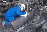
• The supports are correctly oriented for proper functioning.
• All stops, locks, bands, shipping bars, etc. have been removed
• The correct installed load and/or position of the supports has been established (including all required offsets)
During the initial startup phase, perform a second walk down survey to ensure that the piping system is performing as anticipated and thereby allowing the pipe supports to execute their specified applications.
Routine Maintenance: – Walk down surveys performed as part of routine maintenance, should focus on the following:
• The actual operating conditions do not exceed anticipated operating conditions including loading and/or movement of the pipe supports.
• Pipe supports, or any component thereof, have not been damaged during operation.
• The lifespan of the pipe supports have not been exceeded.
• Pipe supports have been properly maintained including lubrication, cleaning and adjustments.
At the Event of Failure or Shut down: – There could be several reasons a system failure or accident happens. When a process upset happens, some imbalanced forces and/or reactions occur throughout the system, and as a result the pipe supports may become imbalanced and fail to function properly. Thus, it becomes important to do a system walk down in order to inspect the functionality of the pipe supports and perform all necessary repairs, adjustments and/or replacements.
test service nolan
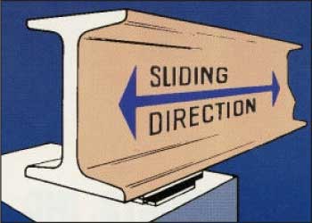
Slide bearing plates are a very cost-effective way of providing for movement of mechanical systems.

Piping Technology & Products, Inc. supplies slide bearing plates for a variety of applications including support of piping, heavy equipment such as pressure vessels, and structural steel members. The plates provide a low coefficient of friction which can be attached to a supporting structure. This combination provides support while simultaneously allowing an object to move (slide) along the supporting surface.
Slide Plates: The “Sandwich” Concept
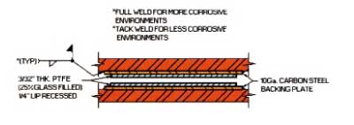
Like other leading designers in our field, Piping technology & Products, Inc. uses the “sandwich concept when applying slide plates to our customers’ system. Figure 1 shows a “sandwich” composed of two identical slide plates, one on top and another on the bottom. Each slide plate is composed of two components: a metal backing plate (which is the bun of the “sandwich”) and a low coefficient of friction material which is bonded to the metal backing plate.
In a typical application a slide bearing plate is welded to a structural steel member which is strong enough to provide the required support, but whose coefficient of friction is too high. Figure 2 shows an application in which a slide bearing plate is welded on top of one steel beam supporting another beam. When the top beam moves (due to thermal expansion, for example) it slide across the surface of the bearing plate without contacting the supporting beam. To return to our “sandwich” metaphor, the top half of the “sandwich” is bonded to the sliding beam, and the bottom half to the supporting beam.
Materials
One combination of materials that we often use is that of PTFE, 25% Glass Filled bonded to stainless steel. Both materials resist oxidation and have long lives even in stressful environments. For large slide plates, galvanized steel can be used in place of stainless to reduce the cost. PTFE, 25% Glass Filled provides a low coefficient of friction for most combinations of temperature and load. Figure 3 shows the recommended conditions for 3/32” PTFE, 25% Glass Filled. Note that a 500 psi load would be at the limit at 400 degrees F.
When the slide bearing plate must function at higher temperatures, graphite can be used instead of PTFE, 25% Glass Filled. The ideal temperature range of graphite is around 1,100 degrees F. For combinations of temperature and load beyond the capabilities of graphite, special designs must be considered.
test service nolan
PT&P’s graphite impregnated bronze slide plate, better known as Bronzphite®, is a self-lubricating bearing plate made up of a high quality bronze with graphite filled grooves.
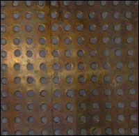
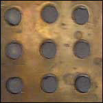
Bronzphite: Construction
Bronzphite® is machined cast bronze plate, provided with solid graphite inserts arranged in various patterns and sizes to meet customer specifications.
Quality of the bronze: Equivalent to UNS C-92400
Chemical Composition: Cu 86-89%, Zn:1-3%, Sn: 9-11%, Pb: 1-2.5%
Physical Properties:
– Tensile strength — 40 ksi min.
– Yield strength — 18 ksi min.
Bronzphite: Application
Bronzphite® is best suited for high loads, low velocity applications and in places where the use of oil or grease is undesirable or unfeasible. The area in which it is utilized, can reach temperatures up to 1100°F.
The bronze plate acts as the bearing surface, withstanding heavy loads, while the graphite inserts provide a solid, oil-free lubricant. The formation of lubricant forms a film of graphite between the bearing and mating surface which results in low co-efficient of friction upon the start of relative motion.
The benefits of having an oil-free lubricant is that the slide plate:
• Is maintenance free
• Withstands extreme pressures and high temperatures
• Is self-lubricating
• Has high wear resistance
• Lubrication does not deteriorate with wear
• Has an extended life
• Prevents unwanted accumulation of dust and debris
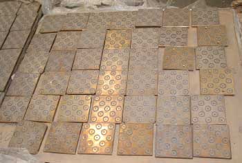
Bronzphite: PT&P’s Capabilities
Piping Technology and Products is a supplier of maintenance free slide bearing plates referred to as Bronzphite®, whose high strengths bearings and impregnated graphite, together create a concoction ideal for maintaining excellent wear resistance and durability under severe operating conditions. PT&P has supplied Bronzphite® for number of companies in the oil, gas and power industry.
For more information about Bronzphite® please call 713-731-0030 or visit our website at www.stg-httpspipingtechcom-stagingdev.kinsta.cloud.
test service nolan
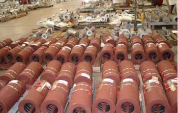
Difference – The major differences between standard springs and furnace springs are in their construction and their intended use. Furnace springs operate in much the same way as other variable spring supports. They are designed to support the pipe or tubes that are subjected to vertical thermal movement. The design changes are necessary because furnace springs are exposed to extreme temperatures.
Coatings – Furnace springs are almost always coated with red oxide primer in order to avoid any potential hazards when exposed to high temperatures. Standard springs are usually hot dipped galvanized, which, when exposed to high temperatures, tends to melt the zinc coating. The molten zinc can then cause damage to the surrounding pipe and equipment.
| FURNACE SPRINGS | STANDARD SPRINGS | |
| COATINGS | Red oxide primer in order to avoid potential hazards when exposed to high temperatures. | Hot dipped galvanized which tends to melt the zinc coating. Molten zinc can damage surrounding pipe and equipment. |
| CONSTRUCTION | • Unique to its application and intended use • Welded design for housing assembly • Centers the spring coils within the housing and accommodates lug attachments |
• Interchangeable • Bolted configuration for the housing |
| DESIGN | Spring used as a means to determine the loading of the catalyst tubes |
Construction – Whereas many of the standard variable spring components are interchangeable, the furnace spring assemblies are constructed from components unique to its application and intended use. The furnace spring incorporates a welded design for the housing assembly unlike standard spring housings that use a bolted configuration. The internal components of the furnace spring are designed to center the spring coils within the spring’s housing to prevent misalignment. In addition, the spring housing is modified to accommodate lug attachments on existing furnace tubing and equipment. Special fabricated casings, spring coils, and nameplates may also be used to accommodate increased travel.

Design – Some furnace springs are designed in order for the spring to be used as a means to determine the loading of the catalyst tubes. In these applications, an exact spring rate is determined for each assembly. The exact spring rate (which may differ slightly from published spring rate values) can then be used to determine the weight of the tubing system in order to balance the unit.
test service nolan
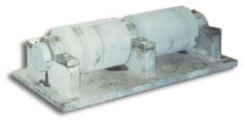
Big Ton Springs are basically like the F-type variables.
test service nolan
 Vibrations produced by rotating machinery are very common for industrial piping systems. Bracing devices can be used to cope with vibration. Hold downs are one of the most widely used pipe support devices to restrain or dampen pipe vibration. A common location for applying a hold down exists near a compressor. The objective is to limit vibration caused by rotating equipment in order to avoid damage to the surrounding piping system. The hold down restrains the vibration introduced by the compressor as it compresses the gases in the pipe line. Hold downs are effective for the control of vibration and/or movement.
Vibration Control: PT&P’s Capabilities
Pipe Technology & Products, Inc. can custom design and fabricate hold downs for any pipe size application. In additional to hold downs, PT&P also offers other types of vibration control devices to accommodate different pipe orientations and locations:
Types:
 Anchor Type (PTP HD-1)
Generally used on pipe lines where little or no insulation is required
Temperature: 750°F
Anchor Type (PTP HD-1)
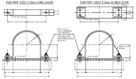
APPLICATION: The PTP Fig. HD-1 is our anchor type hold down. This hold down is generally used in pipe lines where little or no insulation is required.
Material: Carbon Steel
Finish: Black or galvanized
Temperature: 750°F Black Steel
Temperature: 200°C Galvanized Steel
|
Pipe Size
|
A
|
B
|
C
|
D
|
E
|
R
|
T
|
|
2
|
9 3/8
|
3 3/16
|
2 3/8
|
3 1/2
|
15/16
|
1 3/16
|
1/4
|
|
3
|
10 1/2
|
3 3/4
|
3 1/2
|
3 1/2
|
1 1/2
|
1 3/4
|
3/8
|
|
4
|
11 1/2
|
4 1/4
|
4 1/2
|
3 1/2
|
2
|
2 1/4
|
3/8
|
|
6
|
13 5/8
|
5 5/16
|
6 5/8
|
3 1/2
|
3 1/16
|
3 5/16
|
3/8
|
|
8
|
16
|
6 1/2
|
8 5/8
|
3 11/16
|
4 1/16
|
4 5/16
|
3/8
|
|
10
|
19
|
8
|
10 3/4
|
4 1/8
|
5 1/8
|
5 3/8
|
3/8
|
|
12
|
21
|
9
|
12 3/4
|
4 1/8
|
6 1/8
|
6 3/8
|
1/2
|
|
14
|
23
|
10
|
14
|
4 1/2
|
6 3/4
|
7
|
1/2
|
|
16
|
25
|
11
|
16
|
4 1/2
|
7 3/4
|
8
|
1/2
|
|
18
|
27
|
12
|
18
|
4 1/2
|
8 3/4
|
9
|
1/2
|
|
20
|
29
|
13
|
20
|
4 1/2
|
9 3/4
|
10
|
1/2
|
|
24
|
33
|
15
|
24
|
4 1/2
|
11 3/4
|
12
|
1/2
|
|
30
|
39
|
18
|
30
|
4 1/2
|
14 3/4
|
15
|
1/2
|
|
36
|
45
|
21
|
36
|
4 1/2
|
17 3/4
|
18
|
1/2
|
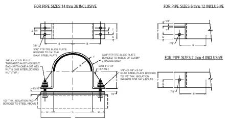
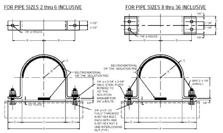
Anchor Type (PTP HD-2)
*generally used on compressor lines or similar applications with high temperature and massive thermal movement
*the clamp radius and the base are line with PTFE slide plate, allowing axial movement while restraining lateral movement.
*Temperature: 400°F
|
Pipe Size
|
A
|
B
|
C
|
D
|
E
|
F
|
G
|
R
|
T
|
|
2
|
9 3/8
|
3 9/16
|
2 1/2
|
3 9/16
|
3/4
|
2 1/2
|
1 1/4
|
1 5/16
|
1/4
|
|
3
|
10 3/4
|
4 1/8
|
3 5/8
|
3 9/16
|
1 5/16
|
2 1/2
|
1 1/4
|
1 7/8
|
1/4
|
|
4
|
11 3/4
|
4 5/8
|
4 5/8
|
3 9/16
|
1 13/16
|
2 1/2
|
1 1/4
|
2 3/8
|
1/4
|
|
5
|
13 7/16
|
5 7/16
|
5 11/16
|
3 7/8
|
2 7/8
|
2 1/2
|
1 1/4
|
2 15/16
|
3/8
|
|
6
|
14 1/2
|
6
|
6 3/4
|
3 7/8
|
2 7/8
|
3 1/2
|
1 1/4
|
3 7/16
|
3/8
|
|
8
|
16 1/2
|
7 9/16
|
8 3/4
|
3 7/8
|
3 7/8
|
3 1/2
|
1 1/4
|
4 7/16
|
3/8
|
|
10
|
18 5/8
|
8 1/16
|
10 7/8
|
3 7/8
|
4 15/16
|
3 1/2
|
1 1/4
|
5 1/2
|
3/8
|
|
12
|
21 3/4
|
9 5/8
|
12 7/8
|
4 7/16
|
5 15/16
|
3 1/2
|
1 1/4
|
6 1/2
|
1/2
|
|
14
|
23
|
10 1/4
|
14 1/8
|
4 7/16
|
6 9/16
|
6
|
1 3/8
|
7 1/8
|
1/2
|
|
16
|
25
|
11 1/4
|
16 1/8
|
4 7/16
|
7 9/16
|
6
|
1 3/8
|
8 1/8
|
1/2
|
|
18
|
27
|
12 1/4
|
18 1/8
|
4 7/16
|
8 9/16
|
6
|
1 3/8
|
9 1/8
|
1/2
|
|
20
|
29
|
13 1/4
|
20 1/8
|
4 7/16
|
9 9/16
|
6
|
1 3/8
|
10 1/8
|
1/2
|
|
24
|
33
|
15 1/4
|
24 1/8
|
4 7/16
|
11 9/16
|
6
|
1 3/8
|
12 1/8
|
1/2
|
|
30
|
39
|
18 1/4
|
30 1/8
|
4 7/16
|
14 9/16
|
6
|
1 3/8
|
15 1/8
|
1/2
|
|
36
|
45
|
21 1/4
|
36 1/8
|
4 7/16
|
17 9/16
|
6
|
1 3/8
|
18 1/8
|
1/2
|
Anchor Type (PTP HD-3)
*generally used on compressor lines or similar applications with low thermal movement
*the clamp radius is lined with a belting material designed to absorb shock from vibration
*Temperature: 200°F
*belting material remains impervious to heat up to 200°F
|
Pipe Size
|
A
|
B
|
C
|
D
|
E
|
R
|
T
|
|
2
|
9 7/8
|
3 7/16
|
2 7/8
|
3 1/2
|
1 3/16
|
1 7/16
|
1/4
|
|
3
|
11
|
4
|
4
|
3 1/2
|
1 3/4
|
2
|
3/8
|
|
4
|
12
|
4 1/2
|
5
|
3 1/2
|
2 1/4
|
2 1/2
|
3/8
|
|
6
|
14 1/8
|
5 9/16
|
7 1/8
|
3 1/2
|
3 5/16
|
3 9/16
|
3/8
|
|
8
|
16 1/2
|
6 3/4
|
9 1/8
|
3 11/16
|
4 5/16
|
4 9/16
|
3/8
|
|
10
|
19 1/2
|
8 1/4
|
11 1/4
|
4 1/8
|
5 3/8
|
5 5/8
|
3/8
|
|
12
|
21 1/2
|
9 1/4
|
13 1/4
|
4 1/8
|
6 3/8
|
6 5/8
|
1/2
|
|
14
|
23 1/2
|
10 1/4
|
14 1/2
|
4 1/2
|
7
|
7 1/4
|
1/2
|
|
16
|
25 1/2
|
11 1/4
|
16 1/2
|
4 1/2
|
8
|
8 1/4
|
1/2
|
|
18
|
27 1/2
|
12 1/4
|
18 1/2
|
4 1/2
|
9
|
9 1/4
|
1/2
|
|
20
|
29 1/2
|
13 1/4
|
20 1/2
|
4 1/2
|
10
|
10 1/4
|
1/2
|
|
24
|
33 1/2
|
15 1/4
|
24 1/2
|
4 1/2
|
12
|
12 1/4
|
1/2
|
|
30
|
39 1/2
|
18 1/4
|
30 1/2
|
4 1/2
|
15
|
15 1/4
|
1/2
|
|
36
|
45 1/2
|
21 1/4
|
36 1/2
|
4 1/2
|
18
|
18 1/4
|
1/2
|
test service nolan
Mechanical Snubbers provided by Piping Technology and Products, Inc. have two modes of operation. In passive mode, i.e., motion caused by thermal loads, the resisting mechanism is disengaged and the snubber “free wheels” with very low resistance. In active mode the mechanism is engaged, and the snubber limits the acceleration to a low threshold value. There are other types of mechanical snubbers, but these are the most common ones.
The Mechanical Snubber Assembly
The snubber operates on the principle of limiting the acceleration of any pipe movement to a threshold level of .02 g’s. This is the maximum acceleration that the snubber will permit the piping to see. Should a disturbance attempt to accelerate the pipe in either direction, a braking force will be applied within the snubber of whatever magnitude required to limit the acceleration to a value less than .02 g’s. At the same time, thermal expansion, being a gradual movement, is not restricted. A particular feature of the snubber is that at no time does it lock and thereby become a rigid strut. Should a sudden acceleration occur and sustain continuously in one direction, the snubber will apply whatever force is necessary to limit the pipe movement to its present threshold value. The snubber’s performance is independent of the amount of force being applied.
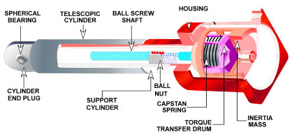
The principle of operation can best be seen in the cross section view above. Two structural telescoping members, colored red and yellow, are connected between the pipe and fixed structure. Within these telescoping tubes is a ball screw and nut which serve to convert the linear telescoping motion, which would occur during a seismic disturbance or thermal changes, to rotational motion of the blue ball screw and drum assembly. This rotational motion is coupled to an inertia mass colored red. The coupling consists of a resilient capstan spring colored orange.
When a disturbance occurs that exceeds the threshold “g” level (.02 g’s), the ball screw and drum attempts to angularly accelerate the inertia mass. The inertial resistance of the mass causes the resilient capstan spring to tighten around a hardened mandrel which is part of the red structural tube. In this manner, a restraining force is applied against rotation of the ball screw, and, in turn, linear telescoping of the silver and red members.
The design of the unit is completely symmetrical, and the same capstan spring will apply this braking action in both the tension and compression loading, which in turn means clockwise or counterclockwise angular acceleration. Therefore, the braking characteristics of the unit in tension and compression are identical.
It can also be noted that when the sudden force is applied, the resisting force is applied by the inertia mass. The inertia mass is mounted to turn freely, and therefore the moment the acceleration drops below the threshold value, it no longer applies a braking force. In additional, the capstan spring is always urging the inertia mass back to an un-braked condition. The net effect is a design which continuously throttles or brakes to limit and control the acceleration. During thermal compensation, the gradual movement, normally associated therewith, is far below the threshold acceleration setting; and therefore, the inertia mass will gradually move without tightening the capstan brake. Should this thermal movement be uneven or jerky as might occur because of a hanger or skid sticking, the unit might momentarily brake, while permitting the pipe movement.
Standard Sizes, Load Rating and Maximum Stroke
| Size | Load Rating | Maximum Stroke |
| MSA – 1/4 | 350 | 4 |
| MSA – 1/2 | 650 | 2 1/2 |
| MSA – 1 | 1500 | 4 |
| MSA – 3 | 6000 | 5 |
| MSA – 10 | 15000 | 6 |
| MSA – 35 | 50000 | 6 |
| MSA – 100 | 120000 | 6 |
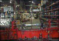
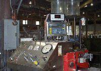
PT&P has two test machines specifically designed for testing snubbers for piping applications, one for routine testing of hydraulic snubbers, and a more sophisticated machine that can perform a wide range of tests on both hydraulic and mechanical snubbers.
PT&P’s STADAS Snubber Test Machine
The STADAS is a trailer mounted snubber test machine manufactured by Paul-Munroe Inc., California. This computer controlled, hydraulic test machine is used to test the performance of mechanical and hydraulic snubbers ranging in size from 150 lb. to 135,000 lb. The STADAS may also be used to verify snubber conditions at the point of manufacture, or during an outage (refueling) at the plant site.
The STADAS machine is capable of controlling a test, following any load sequence needed. It can then plot the test results immediately, and save the results to a disk for future reference.
The main frame of the STADAS machine is comprised of two drive cylinders, which supports the snubber being tested. The smaller drive cylinder is used for snubbers rated to 6000 lb., and the large drive cylinder is used for snubbers rated up to 150,000 lb. Each drive cylinder is equipped with an electro-hydraulic servo-valve load cell and connections to the hydraulic system.
PT&P has two test machines specifically designed for testing snubbers for piping applications, one for routine testing of hydraulic snubbers, and a more sophisticated machine that can perform a wide range of tests on both hydraulic and mechanical snubbers.
test service nolan
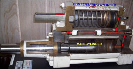
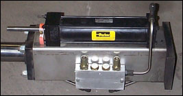
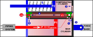
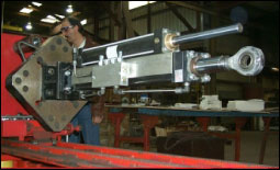
Most hydraulic snubbers have a piston which is relatively unconstrained in motion at low displacement rates. At high displacement rates the piston “locks up”, that is, the force required to move the piston increases substantially, usually as a result of the closing of a valve.
Some of the features include:
• External pressurized hydraulic reservoir for positioning flexibility in any spatial orientation.
• Allows free thermal movement of piping under normal operations.
• Restrains shock loading, both in tension and compression.
• System’s movement is controlled by a flow control device.
Standard Sizes of PT&P Hydraulic Snubbers
| Bore (in.) | Rod Diameter (in.) | Max Recom. Loads (lb.) |
| 1.5 | 1 | 3000 |
| 2.5 | 1.75 | 10000 |
| 3.25 | 2 | 20000 |
| 4 | 2.5 | 30000 |
| 5 | 2 | 50000 |
| 6 | 2.5 | 70000 |
| 8 | 3.5 | 130000 |
PT&P offers seven sizes with cylinder bores of 1 1/2 to 8 inches. These units have a normal load range of 3,000 lbs to 130,000 lbs. All are made to include reservoirs in 6, 12, or 18 inch strokes. Snubbers, as they are sometime referred to, are available with remote reservoirs.
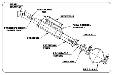
Application
For use on piping systems or equipment when restrained thermal movement must be allowed, but which must be restrained during impulsive or cyclic disturbance. The unit is not effective against low amplitude, high frequency movement. Preferred usage, with standard settings, to prevent destructive results due to earthquakes, flow transients, or wind load. Special settings are available to absorb the continuous thrust resulting from safety valve blow-off or pipe rupture. For the most effective operation of the unit, please specify the mounting position, vertical or horizontal.
Ordering
Please specify figure no., cylinder size, stroke, load, cold, and hot pistons settings, and piston end option. If clamp is required, please specify nominal pipe size, or special O.D. and clamp material. Specification or description of any additional optional features or special settings is required.
Dimensions
| Cylinder Size | Stroke (in.) | A | B Min. | C Min. | C Max. | Max. Recom. Normal Load (lb.) |
| 1 1/2 | 6 | 2 1/6 | 1 5/8 | 15 1/2 | 20 1/2 | 3000 |
| – | 12 | – | – | 19 1/2 | 29 1/2 | – |
| – | 18 | – | – | 19 1/2 | 29 1/2 | – |
| 2 1/2 | 6 | 2 1/2 | 2 1/4 | 15 7/8 | 20 7/8 | 10000 |
| – | 12 | – | – | 19 1/2 | 29 1/2 | – |
| – | 18 | – | – | 19 1/2 | 29 1/2 | – |
| 3 1/4 | 6 | 3 1/4 | 3 | 17 5/8 | 22 5/8 | 20000 |
| – | 12 | – | – | 22 5/8 | 32 5/8 | – |
| – | 18 | – | – | 22 5/8 | 32 5/8 | – |
| 4 | 6 | 4 | 3 3/4 | 19 1/2 | 24 1/2 | 30000 |
| – | 12 | – | – | 24 1/2 | 34 1/2 | – |
| – | 18 | – | – | 24 1/2 | 34 1/2 | – |
| 5 | 6 | 5 1/18 | 4 1/2 | 21 | 26 | 50000 |
| – | 12 | – | – | 26 | 36 | – |
| – | 18 | – | – | 26 | 36 | – |
| 6 | 6 | 5 3/4 | 5 1/2 | 23 5/8 | 28 5/8 | 70000 |
| – | 12 | – | – | 28 5/8 | 38 5/8 | – |
| – | 18 | – | – | 28 5/8 | 38 5/8 | – |
| 8 | 6 | 7 1/4 | 6 | 28 7/8 | 33 7/8 | 130000 |
| – | 12 | – | – | 33 7/8 | 43 7/8 | – |
| – | 18 | – | – | 33 7/8 | 43 7/8 | – |
*Loads must not be applied outside a 10° included angle cone of action to the pipe clamp axis w/o special authorization
E-takeout for Fig. 2100 Hydraulic Snubbers and Sway Strut Assemblies
| Pipe Size | 1 1/2 | 2 1/2 | 3 1/4 | 4 | 5 | 6 | 8 |
|
3/4
|
2 7/16 | – | – | – | – | – | – |
|
1
|
2 9/16 | – | – | – | – | – | – |
|
1 1/4
|
2 11/16 | – | – | – | – | – | – |
|
1 1/2
|
4 1/8 | – | – | – | – | – | – |
|
2
|
5 1/8 | 5 | 6 3/8 | 6 3/8 | – | – | – |
|
2 1/2
|
5 3/8 | 6 1/2 | 7 | 7 1/2 | 8 1/8 | – | – |
|
3
|
5 15/16 | 7 | 7 | 7 1/2 | 8 3/8 | – | – |
|
4
|
6 1/2 | 7 | 7 1/4 | 7 1/4 | 8 3/8 | – | – |
|
5
|
7 | 7 | 7 3/4 | 7 3/4 | 9 1/8 | – | – |
|
6
|
8 9/16 | 8 9/16 | 9 1/4 | 9 1/4 | 10 | 11 | – |
|
8
|
9 9/16 | 9 9/16 | 10 1/8 | 10 1/8 | 11 1/4 | 12 | – |
|
10
|
10 7/16 | 10 7/16 | 11 3/8 | 11 3/8 | 12 3/4 | 14 1/4 | 15 |
|
12
|
– | 11 4/9 | 12 4/7 | 12 4/7 | 13 7/8 | 15 | 15 3/4 |
|
14
|
– | 12 11/18 | 13 1/2 | 13 1/2 | 14 1/2 | 15 | 16 1/2 |
|
16
|
– | 13 2/3 | 14 7/8 | 14 7/8 | 15 1/4 | 16 | 17 1/2 |
|
18
|
– | 14 11/16 | 15 1/2 | 15 1/4 | 16 3/4 | 16 3/4 | 18 1/2 |
|
20
|
– | 15 7/8 | 15 7/8 | 16 1/2 | – | – | – |
|
24
|
– | 17 7/8 | 17 7/8 | 19 5/16 | 20 | 22 | 22 |
|
30
|
– | 23 3/8 | 23 3/8 | 23 3/4 | 24 1/4 | 25 | 26 1/4 |
|
36
|
– | 28 3/4 | 28 3/4 | 28 3/4 | 30 3/4 | 32 3/4 | 32 3/4 |
 |
 |
| Schematic of Hydraulic Snubber under normal conditions |
Schematic of Hydraulic Snubber under locked conditions |
Hydraulic Snubber Test Machine
The Hydraulic Snubber test machine is mainly used to perform testing for hydraulic snubbers, it has a similar test bed to the STADAS machine, however, it is not computer controlled. It is adequate to perform all the tests normally required for hydraulic snubbers, such as quality control and periodic tests that are sometimes required as part of plant maintenance programs. Mechanical snubbers can also be tested on this machine, but due to the complication of the process, mechanical snubbers testing is usually performed on the STADAS machine.
test service nolan
Objective
To show the results of temperature and stress analysis in three pipe support shoes intended for cryogenic operation
It is necessary to know the temperature distribution for cryogenic conditions because most steels lose ductility as the temperature decreases from normal operating conditions. That is, the steel becomes more brittle.
Any steel structure will have local areas of high stress. This may be caused by, for example, sharp corners in the design, or by inclusions in the material. At normal temperatures the material in the region of these concentrations will yield, redistributing the load locally. Typically these have no significant effect on the integrity of the structure as a whole. In brittle materials, the material cannot yield, so the only alternative is for it to form a crack. Frequently, once the crack has been formed, it will propagate at the approximate speed of sound until it reaches the end of the part, thus causing a catastrophic failure.
Further complicating the picture is the fact that the tendency for brittle fracture increases with part thickness, and this increase is temperature dependent. Clearly, temperature is a critical variable in selecting steels for cryogenic applications.
The three shoes considered are of the same basic design, but are for three different pipe sizes: 6, 20, and 42 inch. The basic design is shown in Figure 1.
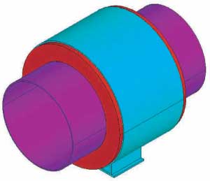
The shoes have three major components. They are:
1. An outer cover and base of carbon steel, shown in Figure 2A. This has ring stops at either end to engage the insulation to keep it from moving. A point of particular concern was the temperature and stress of the steel on the inner surface of this ring.
2. A pipe which carries the cryogenic fluid. This has an attached ring of stainless steel, again for engaging the insulation. This is shown in Figure 2B.
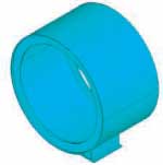
3. The polyurethane foam insulation (PUF) between the first two parts, shown in Figure 2C. As illustrated, the insulation has outer grooves for the shell ring stops, and an inner groove for the pipe ring.
 |
 |
 |
Figure 2A: Shell |
Figure 2B: Pipe and Ring |
Figure 2C: Insulation |
STRESS & THERMAL ANALYSIS
The stress and the thermal analyses are, for the most part, quite similar. The finite element program, Ansys was used for both. There are two main differences between the analyses. Primarily, the material properties are different. Young’s modulus vs. thermal conductivity, for example; the other main difference is in the choice of elements. In this case we used Ansys element 92 for the stress analysis, and thermal element 83. These are both 10 node tetrahedral solid elements. The primary difference is that the thermal element has only one degree of freedom at each node (for temperature), while the stress element has three, one for x, y, and z displacements.
STRESS ANALYSIS
The main concern in the 42 inch pipe shoe case was the inner surface of the outer retaining rings. If the temperature is too low for the stress, the specified steel may not be appropriate according to the code.
The other two cases are very similar to this one and those stress results are given in Appendix A.
Applied loads for all three cases are given in Table1. Note that while the loads were specified in kN, the actual computations were done in inches and pounds, and the results are reported in those units.
Table 1: Applied loads for the stress analysis of the three shoes
|
Pipe Size
|
Axial Load
|
Vertical Load
|
Lateral Load
|
|
42 in
|
600 kN
|
175 kN
|
70 kN
|
|
20 in
|
275 kN
|
65 kN
|
50 kN
|
|
6 in
|
43 kN
|
25 kN
|
10 kN
|

STRESS ANALYSIS
Figure 4 shows an overview of the stresses on the shell and base, and Figure 5 shows a detail of the stresses in the area of maximum stress. The stresses in the shell are generally quite low. However, at the intersection of the base with the cylindrical shell there is a local stress concentration with somewhat higher stresses. This should not be a problem at this location. As we shall see, the temperature here is quite high, as compared to the rest of the shoe.
 |
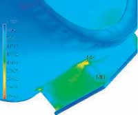 |
Figure 4: Stresses in shell and base |
Figure 5: Detail of stresses in the
|
The stresses in the pipe and its ring are shown in Figure 6. The stresses are largest where they would be expected, at the intersection of the two.
STRESS ANALYSIS
In Figures 7 and 8 we show the stresses in the insulation. Figure 7 is an overview. Figure 8 is a cut away view showing stresses on the inside. The fact that the stress is mostly in the bottom quarter is the result of the significant vertical load.
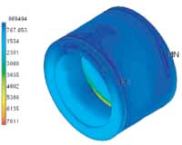 |
 |
Figure 7: Stresses in the insulation |
Figure 8: Section detail of insulation stresses |
THERMAL RESULTS
For all three shoes, the thermal conditions were the same. The inner surface of the pipe was -270°F. The ambient air temperature was -20°F, with a wind velocity of 78.74 in/sec (2 m/sec). Based on this wind speed, and the diameter of the outside shield, we computed a film heat transfer coefficient. The values for the three cases are shown in Table 2.
Table 2: File heat transfer coefficients used in the study
|
Pipe Size
|
Coefficient
|
|
42 in
|
0.008281 BTU/ in2 hr
|
|
20 in
|
0.009651 BTU/ in2 hr
|
|
6 in
|
0.01190 BTU/ in2 hr
|
The values of thermal conductivities used are in Table 3. Note that for the 32 lb PUF case the coefficient is linear with temperature. For the 20 Lb PUF we had only one data point, so we were unable to use a temperature dependent relation.
Table 3: Thermal conductivities for materials used in the study
|
Material
|
Conductivities in BTU /hr in oF
|
|
Carbon Steel
|
2.645
|
|
Stainless Steel
|
0.7846
|
|
32 Lb PUF
|
.0.003007-0.000003627*T
|
TEMPERATURE DISTRIBUTION
In Figure 9 we show the temperature for the complete assembly. As expected, the temperature on the pipe is the specified temperature, and the temperature on the base is slightly lower than the ambient.
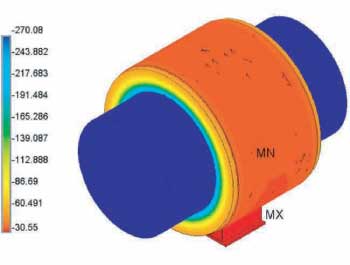
Again, it is helpful to look at the individual parts. Figure 10 shows the temperature on the shell and base. The coldest temperature is greater than -40°F, and thus much higher than the temperature that would cause concern.
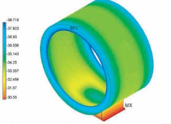
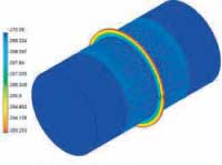
TEMPERATURE DISTRIBUTION
In Figures 11 and 12 we show the temperature distributions on the other two parts. There is nothing particular to note concerning these plots. (Temperatures are °F)
 |
 |
Figure 11: Ring and Pipe |
Figure 12: Insulation |
Figure 13 shows the interface between the steel and the insulation. As expected, the temperature in both the inner and outer rings is little affected by the temperature in the surrounding insulation, and is nearly the same as if there were no insulation present.

The report includes both the temperature and the stress at each point of the shoe assembly. This should be adequate for a proper selection of steels for the design.
APPENDIX A
In this Appendix we show the results of the stress analyses of the 20 and 6 in. pipe cases. There is little to add to what has been said about the 42 in. case.

 |
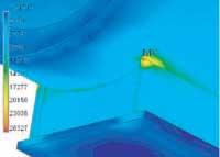 |
Figure A2: Stresses in shell-base part |
Figure A3: Detail of maximum stress |
 |
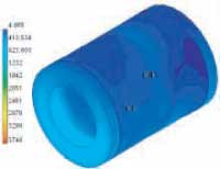 |
Figure A4: Stresses in ring pipe |
Figure A5: Stresses in insulation |

 |
 |
Figure A8: Shell-Base stresses, 6 inch case |
Figure A9: Detail at maximum stress |
 |
 |
Figure A10: Stresses in pipe and ring |
Figure A11: Stresses in 6 inch insulation |
 |
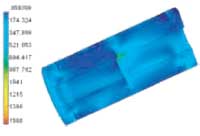 |
Figure A13: Detail of ring |
Figure A12: Stresses on insulation section |
At the left, we show a expanded view of the ring – pipe intersection. The high stresses shown in Figure A10 are very local, and only near the pipe end. This is where the loads were applied. The total load is correct, and, as can be seen, stresses near the intersection are more moderate.
APPENDIX B: Temperature Distribution
Note: Temperatures are degrees °F


test service nolan
PT&P manufactures a range of standard clamps covering common pipe sizes. These are made of carbon steel and either galvanized or left black. In addition, we frequently fabricate custom clamps for special applications. Applications examples include high temperatures requiring alloy steel, or those requiring nonstandard dimensions.
In these analyses, we have assumed that the bending radius of forming the ears is 1.5 times the plate thickness. This is the value calculated and used as a practice at PT&P. The AISC recommends that the values are three times the thickness of the plates of 1 to 1-1/2” thickness and four times the thickness for greater thickness. The Finite Element Analysis demonstrates that larger radiuses would result in lower stresses. These cases prove that Finite Element Analysis at PT&P has led to significantly lower costs to our customers by justifying the use of less steel.
FEA & Specially Designed Clamps
Recently, a stress analysis was conducted of an 82 plastics pipe constrained in the axial direction by a special pipe clamp. PT&P’s final design assumes that three clamps in a series will resist at a total expected axial force of 8,000 lbs. Since the area of the pipe in contact with the support affects the overall stress distribution, it is necessary to determine how much contact there is at different pressures via FEA in two steps.
Step #1
The first step establishes whether or not the stresses in the clamp and pipe

were in acceptable limits and fixes a starting condition for the remainder of the analysis. Here, the clamping force (estimated to be 13,300 lbs.) alone acted upon the clamp and pipe. The initial design of the clamp indicated stresses exceeding permissible boundaries by being greater than 50,000 psi. The design was thus modified to alleviate the problem.
Step #2
This step involves determining the highest load achieved before slipping.
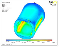
Figure 1 shows stresses on the complete assembly and points that the maximum stress on the clamp is 28,800 psi. The high stress is localized in very small areas at the tip of the gusset. In Figure 2, we have plotted stresses in the plastic pipe only. The maximum stress in the pipe is an acceptable 2,360 psi.
Summary
The maximum stress on the clamp is determined to be 28,800 psi. Stresses in Figure 1 would normally be of little concern in mild steel at typical operating temperatures. If it were a problem, extending the gussets upwards is recommended. In addition, it is recommended to increase pipe length if higher stress is desired. This is due to increased contact between the pipe and clamp, which spreads stress over more area allowing for greater pressures.
test service nolan
Pipe Clamps
PT&P manufactures a range of standard clamps covering common pipe sizes. These are made of carbon steel and either galvanized or left black. In addition, we frequently manufacture custom clamps for special applications. Examples of such applications are high temperatures requiring alloy steel, or applications requiring nonstandard dimensions.
PT&P normally analyzes such special designs using Finite Element Analysis. One reason for this is to ensure that the design has sufficient strength to support expected loads. This is also done to see if the clamp can be made more economically and still function satisfactorily.
FEA & Specially Designed Clamps
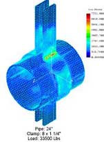
Recent examples include two Figure 80 type clamps for a high temperature application. Figure 80 clamps are heavy-duty three-bolt pipe clamps. Due to the high temperature duty, they were made from alloy steel, A387 Grade 91. This steel contains 9% Chromium, 1% Molybdenum and small amounts of Niobium and Vanadium. Both clamps are for 24” pipes, one for a load of 68,200 lbs., and one for 33,500 lbs.
Results: Clamp Test #1
The initial FEA was conducted on the clamp designed to sustain a load of 68,200 lbs. For this load, the PT&P Clamp Sizing program called for a clamp made from two 2” thick x 12” wide strips of steel. This case required the FEA find a maximum stress of 6150 psi. This is considerably less than
the allowable stress for the steel at the operating temperature. As a result, the clamp thickness was reduced to 1-1/2“. It was confirmed that the stresses were again below the allowable.

Results: Clamp Test #2
The second FEA was conducted on a clamp designed for a load of 33,500 lbs. According to PT&P’s standard sizing program, this clamp’s design was made from 1-1/2” x 10” steel. The FEA found a maximum stress of 4250 psi, well below the 10,300 psi allowable. Thus, PT&P engineers reduced the size of the clamp to 1-1/4” x 8”, with resulting stress of 7331 psi.
Conclusions
In these analyses, we have assumed that the bending radius of forming the ears is 1.5 times the plate thickness. This is the value calculated and used as a practice at PT&P. The AISC recommends that the values are three times the thickness of the plates of 1 to 1-1/2” thickness and four times the thickness for greater thickness. The Finite Element Analysis demonstrates that larger radiuses would result in lower stresses. These cases prove that Finite Element Analysis at PT&P has led to significantly lower costs to our customers by justifying the use of less steel.
test service nolan
FEA: Case Studies
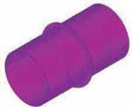
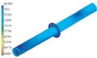
Product: Transition Piece
Technical Information: 3D Modeling Software, Parametric Technologies Modeler, Finite Element Analysis Software, COSMOS
Case Study Information
This item was modeled to the specifications included in drawing 6819001-159020. It uses a standard flange at the top as specified. It has been modified to include the extra length of pipe and to eliminate two flanges. The rectangular flange is fabricated of 1.25 x 5 inch stock and is made of A36 steel. The whole transition and pipe is fabricated of 3/8” thick A516 Grade 70 steel and this was expressed in the model. The model has a temperature condition of 105° C/221°F.
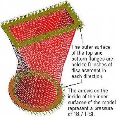
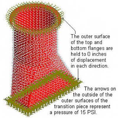
Two cases were modeled in which all references to pressure, PSI, refers to PSIG (PSI gage). The first was at operating condition when the transition piece experiences 18.7 PSI internal pressure. The second was at full vacuum when the transition piece experiences 15 PSI external pressure. The stress and displacement results are expressed in the following plots.
*Note: All references to pressure, PSI, refers to PSIG (PSI gage)
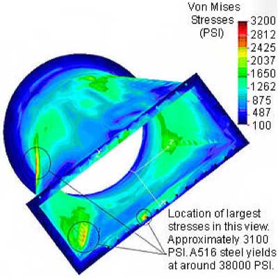
Illustration of Pressures and Displacements – Transition Piece: Internal Pressure = 18.7 PSI
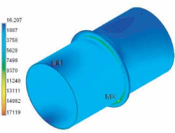
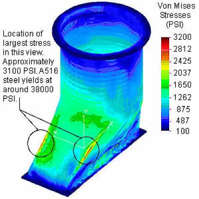
Stress Plot #1 – Transition Piece: Internal Pressure = 18.7 PSI
This model has an internal pressure of 18.7 PSI on every internal surface. The chart on the left of the model shows the stresses at every point in the model by a color coding system.
Stress Plot #2 – Transition Piece: Internal Pressure = 18.7 PSI
This model has an internal pressure of 18.7 PSI on every internal surface.
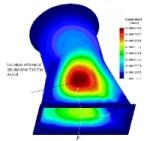
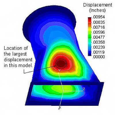
Displacement Plot #1 – Transition Piece: Internal Pressure = 18.7 PSI
This model has an internal pressure of 18.7 PSI on every internal surface. The chart shows the displacement at every point in the model by a color coding system which represents inches of displacement.
Illustration of Pressures and Displacements – Transition Piece: External Pressure = 15 PSI
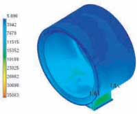
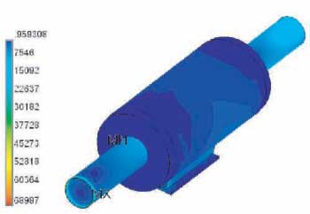
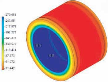
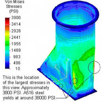
Stress Plot #1 – Transition Piece: External Pressure = 15 PSI
This model has an external pressure of 15 PSI on every external surface. The chart above shows the stresses at every point in the model by a color coding system.
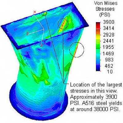
Stress Plot #2 – Transition Piece: External Pressure = 15 PSI
The chart above shows the stresses at every point in the model by a color coding system. This model has an external pressure of 15 PSI on every external surface.
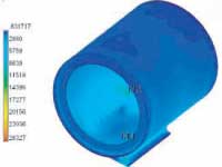
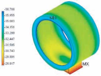
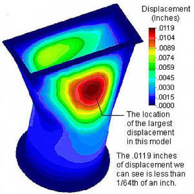
Displacement Plot #1 – Transition Piece: External Pressure = 15 PSI
The chart above shows the displacement at every point in the model by a color coding system which represents inches of displacement.