Hydraulic Snubbers Designed for a Steam Generator in Mexico

test service nolan

Hydraulic Snubbers Designed for a Steam Generator in Mexico

Type: Hydraulic Snubbers
Size: 24″ up to 30″ Pin-To-Pin | Cylinder Dia. 1.5″ to 3.25″
Material: Carbon Steel
Design: 3,000 lb. to 20,000 lb., with a 6″ Stroke
Testing: Standard Quality Control

PT&P designed Fig. 510 AD short strut hydraulic snubbers for a steam generator at a facility in Mexico. The snubbers ranged in length from 24″ up to 30″ pin-to-pin with cylinder diameters of 1.5″ to 3.25″. A total of 48 snubbers were fabricated from carbon steel and designed for an operating load ranging from 3,000 lb. to 20,000 lb., with a 6″ stroke. Snubbers are used for systems where unrestrained thermal movement must be allowed except during cyclic disturbance. Hydraulic snubbers are designed to protect the piping system when a sudden, heavy load is applied (such as an earthquake of high intensity), which can cause serious vibrations leading to damage and possible failure of the piping system.

Pre-Insulated Cryogenic Supports for Propylene Dehydrogenation

test service nolan

Pre-Insulated Cryogenic Supports for a Propylene Dehydrogenation Application at a Petrochemical Plant in Texas

Type: Pre-Insulated Cryogenic Supports
Size: 12” Long Base | 32” Wide Base | 62″ Overall Height | 18” Long Insulation
Material: Polyurethane | Carbon Steel w/ HDG Finish
Design: Operating Temperature -360°F & 42″ NPS
Testing: Standard Quality Control

Piping Technology and Products, Inc. and custom designed two pre-insulated cryogenic supports for a propylene dehydrogenation application at a petrochemical plant in Texas. The insulation is made from a high density polyurethane insulation, with the bearing plates and side bumpers fabricated from carbon steel with an HDG finish. The shoes are capable of insulating and supporting at temperatures as low as -360°F. These were designed to support pipeline diameter of 42” with overall height of 62” diameter. Regular quality control tests were performed with a standard turn-around time.

Support Assembly Components

test service nolan

Piping Technology & Products, Inc. maintains an extensive inventory of components required for pipe hanger and
support assemblies. Most of these are industry standards that have been used by piping designers for many
years. One of the value-added services we provide is assembly and tagging of units before shipping so field crews
can install them with minimal effort. Since we work with these materials every day, assembling and verifying components and dimensions is more efficient for us compared to a field crew, for whom installing pipe supports is just one of many tasks they must complete during a typical workday.

Many assemblies are attached to the pipe with clamps. Our inventories include all types of clamps made from
carbon steel with galvanized and black finishes. We can fabricate clamps from alloy steels for high-temperature
applications in which standard clamps are not adequate. When ordering clamps, please add an “A” to the figure
number of any items to be fabricated from alloy material.

To compensate for pipe movement, a designer may choose from a variety of clevis hangers, roller hangers, and
adjustable bands to support the pipe. These are linked to the supporting structure with rods and other hardware
components. Beam attachments and other accessories are attached to the supporting structure to complete the
assembly. All of these components must be strong enough to support the loads in the environment where they are
installed. Galvanized components are often used to resist corrosion.

Saddle coverings are used with insulated pipes in order to provide protection to the insulation at points of support.
Roller stands, elbow supports, and other items can be supplied in adjustable models which allow field crews to make
easy installations.

Hold-downs are special clamping supports used on pipes that are subject to vibrations and stresses, such as those
near compressors. The hold-downs dampen these forces by transferring them to the supporting structure and thus
protect the piping system.


Pipe Saddles & 30″ Galvanized Riser Clamp

Nominal Insulation Table (Size vs. Actual)

test service nolan

NOMINAL INSULATION THICKNESS (in.)INSULATION O.D. (in.)APPROX. INSULATION THICKNESS (in.)

Pipe size: 1/2" (O.840 O.D.)

12 7/81
1 1/241 9/16
252 1/16
2 1/26 5/82 7/8
37 5/83 3/8
3 1/28 5/83 7/8
49 5/84 3/8

Pipe size: 3/4" (1.050 O.D.)

12 7/87/8
1 1/241 7/16
251 15/16
2 1/26 5/82 3/4
37 5/83 1/4
3 1/28 5/83 3/4
49 5/84 1/4

Pipe size: 1" (1.315 O.D.)

13 1/21 1/16
1 1/24 1/21 9/16
25 9/162 1/8
2 1/26 5/82 5/8
37 5/83 1/8
3 1/28 5/83 5/8
49 5/84 1/8

Pipe size: 1 1/4" (1.66 O.D.)

13 1/215/16
1 1/251 11/16
25 9/161 15/16
2 1/26 5/82 1/2
37 5/83
3 1/28 5/83 1/2
49 5/84

Pipe size: 1 1/2" (1.90 O.D.)

141 1/16
1 1/251 9/16
26 5/82 3/8
2 1/27 5/82 7/8
38 5/83 3/8
3 1/29 5/83 7/8
410 3/44 7/16

Pipe size: 2" (2 3/8" O.D.)

14 1/21 1/16
1 1/25 9/161 9/16
26 5/82 1/8
2 1/27 5/82 5/8
38 5/83 1/8
3 1/29 5/83 5/8
410 3/44 3/16

Pipe size: 2 1/2" (2 7/8" O.D.)

151 1/16
1 1/26 5/81 7/8
27 5/82 3/8
2 1/28 5/82 7/8
39 5/83 3/8
3 1/210 3/43 15/16
411 3/44 7/16

Pipe size: 3" (3 1/2" O.D.)

15 9/161
1 1/26 5/81 9/16
27 5/82 1/16
2 1/28 5/82 9/16
39 5/83 1/16
3 1/210 3/43 5/8
411 3/44 1/8

Pipe size: 3 1/2" (4" O.D.)

16 5/81 5/16
1 1/27 5/81 13/16
28 5/82 5/16
2 1/29 5/82 13/16
310 3/43 3/8
3 1/211 3/43 7/8
412 3/44 3/8

Pipe size: 4" (4 1/2" O.D.)

16 5/81 1/16
1 1/27 5/81 9/16
28 5/82 1/16
2 1/29 5/82 9/16
310 3/43 1/8
3 1/211 3/43 5/8
412 3/44 1/8

Pipe size: 4 1/2" (5" O.D.)

17 5/81 5/16
1 1/28 5/81 13/16
29 5/82 5/16
2 1/210 3/42 7/8
311 3/43 3/8
3 1/212 3/43 7/8
4144 1/2

Pipe size: 5" (5 9/16" O.D.)

17 5/81
1 1/28 5/81 1/2
29 5/82
2 1/210 3/42 9/16
311 3/43 1/16
3 1/212 3/43 9/16
4144 3/16

Pipe size: 6" (6 5/8" O.D.)

18 5/815/16
1 1/29 5/81 7/16
210 3/42
2 1/211 3/42 1/2
312 3/43
3 1/2143 5/8
4154 1/8

Pipe size: 7" (7 5/8" O.D.)

19 5/81
1 1/210 3/41 1/2
211 3/42
2 1/212 3/42 1/2
3143 1/8
3 1/2153 5/8
4164 1/8

Pipe size: 8" (8 5/8" O.D.)

110 3/41 1/16
1 1/211 3/41 1/2
212 3/42
2 1/2142 5/8
3153 1/8
3 1/2163 5/8
4174 1/8

Pipe size: 9" (9 5/8" O.D.)

111 3/41 1/16
1 1/212 3/41 1/2
2142
2 1/2152 5/8
3163 1/8
3 1/2173 5/8
4184 1/8

Pipe size: 10" (10 3/4" O.D.)

112 3/41
1 1/2141 9/16
2152 1/16
2 1/2162 9/16
3173 1/16
3 1/2183 9/16
4194 1/16

Pipe size: 11" (11 3/4" O.D.)

1141 1/8
1 1/2151 9/16
2162 1/16
2 1/2172 9/16
3183 1/16
3 1/2193 9/16
4204 1/16

Pipe size: 12" (12 3/4" O.D.)

1151 1/8
1 1/2161 9/16
2172 1/16
2 1/2182 9/16
3193 1/16
3 1/2203 9/16
4214 1/16

Pipe size: 14" (14" O.D.)

1162
1 1/2171 7/16
2181 15/16
2 1/2192 7/16
3202 15/16
3 1/2213 7/16
4223 15/16
Large sizes, insulation O.D. are in 1" increments.

Insulation thicknesses through 36" same as nominal.

All dimensions rounded to the nearest 1/16".

Instrument Supports – Welded and Adjustable Components

test service nolan

PT&P offers a complete line of adjustable instrument support components which, when combined, will create various configurations to your exact requirements or individual needs. We also provide welded instrument supports fabricated according to your specifications.

Welded instrument stand
Welded Instrument Support / Stand

Adjustable instrument stand
Adjustable Instrument Support / Stand

ADJUSTABLE INSTRUMENT SUPPORTS COMPONENTS

Primary support components are available in various mount styles, including floor mounts, wall mounts, u-bolt mounts, and cable mounts. These primary mounts can be used independently or together with secondary components to construct various packages for individual needs.

PTP-IS-600
PTP-IS-600
Primary component has a 2” pipe extension 54” long, designed for grade mounting of  instrument assemblies, comes with slotted hole in base.

PTP-IS-610
PTP-IS-610
Primary component has a 2” square extension
16” long, designed for mounting on vertical or
horizontal lines.

PTP-IS-620
PTP-IS-620
Primary component has a 2” pipe, at a right angle with a vertical leg, designed for mounting on vertical lines.

PTP-IS-630
PTP-IS-630
Primary component has a 2” pipe, at a right angle with a vertical leg, designed for mounting on horizontal lines.

PTP-IS-640
PTP-IS-640
Female adaptor with two 2” extension 2” long, provides female connection to 2” pipe components, used for constructing multiple instrument support systems.

PTP-IS-650
PTP-IS-650
Adaptor with 2” pipe extension 8” long.

PTP-IS-660
PTP-IS-660
2” square extension component, 16” long, with 2” u-bolt mount, for constructing various instrument support configurations.

PTP-IS-670
PTP-IS-670
2” square component, 24” long designed for use in constructing multiple support mounts and other applicable configurations as required.

PTP-IS-680
PTP-IS-680
Secondary component, with 2” u-bolt mount,
provides auxiliary equipment mount and/or flag for identification.

PTP-IS-690
PTP-IS-690
Primary component, 2” square extension 16” long, designed for mounting on walls and columns.

Note: The extension lengths shown on primary components are standard, other lengths can be furnished on request.

WELDED INSTRUMENT SUPPORTS

Welded instrument supports may be fabricated in any desired configuration according to the customer’s individual requirements and design specifications.

Examples of various welded instrument support configurations:

Welded Instrument Support Configuration
Welded Instrument Support Configuration (Diagram A)

Welded Instrument Support Configuration
Welded Instrument Support Configuration (Diagram B)

Welded Instrument Support Configuration
Welded Instrument Support Configuration (Diagram 2A)

Welded Instrument Support Configuration
Welded Instrument Support Configuration (Diagram 2B)

Instrument Supports Selection Chart

Cable Mounts
U-Bolt Mounts
Wall Mounts
Floor Mounts
Secondary Supports
Attachment:
Attached to instrument by cable.
Attached to piping instrumentation.
Welded or bolted to support.
Attached to instrument; welded or clamped on stand.
Function:
Support and hold instrument at fixed location.
Hold instrument during plant operation.
Support instrumentation during operations.
Used in combination with primary supports to support instrumentation.
Location:
Where instrument is welded to structure
Bolted into concrete or welded to structure.
Bolted to walls and other vertical surfaces.
Bolted on the floor or in the ground.
Attached to primary instrument stands, usually floor or wall mounts.

Marinite® Technical Information

test service nolan

Marinite can be used as the insulating material in hot piping supports. The most widely known grade for Marinite is grade P. Marinite-P is most often used as structural insulation because of its high dimensional stability. Marinite-P is incombustible, provides high insulation values, and high compressive strengths and is thus appropriate in high-load and high-temperature applications. The material minimizes decay, rust, and corrosion and it resists damage during installation and provides durable service. The material acts as a suitable insulator in fireproofing and heat processing equipment applications up to 1200°F (649°C).

Major Advantages:
• High Compressive Strength.
Deflects less than 1/10 in. per inch of thickness under 4000 psi
Deflects less than 3/64 in. per inch of thickness under 2000 psi
• High Tensile strength.
• High resistance to shear and traverse forces.

Major Applications:
• Hot Line Pipe Supports in Power Generation and Process Industries
• Structural Insulation in Pipe
• Supports Backup Insulation in Rotary Kilns of Lime and Cement Plants.
• Ceramics and Foundry applications.

Coefficient of Friction:
0.08 @ minimum pressure
0.06 @ maximum pressure

Firetemp® Technical Information

test service nolan

Firetemp®, usually known as Super Firetemp®, is widely used as insulation for hot piping supports. It is an inorganic incombustible material. Chemically, it features a xonotlite crystal structure that results in exceptional strength and extremely low water if hydration. Super Firetemp®  is composed primarily of lime, silica, and reinforcing fibers. The product is white, essentially dust-free, and contains no asbestos. It is a very good material for structural insulation inserts.

Firetemp®  insulation’s major advantages and applications are given below. For more detail please see the Insulation Comparison Table.

Major Advantages:
• Exceptionally High Strength
• Low Conductivity
• Easy Application
• Zero clearance to combustibles
• Temperature Range to 1800°F
• Asbestos-Free

Major Applications:
• Hot Line Pipe Supports in Power Generation and Process Industries
• Indoor and Outdoor Piping and Equipment
• Block Insulation
• Fire rated enclosures around kitchen exhaust hood
• Fireproofing structural steel
• Fire rated walls

Foamglas® Technical Information

test service nolan

Foamglas® insulation is a lightweight, rigid insulation composed of millions of completely sealed glass cells. Each cell serves as an insulating agent. Foamglas® is widely used in the cryogenic and hotline pipe supports and is fabricated in various ranges of shapes, thicknesses, and sizes to meet the particular requirements of an application.

One unique advantage that Foamglas® has is its very low moisture absorption. Since Foamglas® insulation is full of closed glass cells, it resists moisture in both liquid and vapor form. This guarantees the long-term performance of the insulation. Foamglas® insulation’s resistance to moisture ensures that properly installed, it retains its original thermal efficiency.

The major advantages and applications of Foamglas® insulation are listed below. For details about the physical and mechanical properties of the Foamglas® material, please refer to the table.

Major Advantages:
•Constant Insulating Efficiency
•Fire Protection
•Corrosion Resistance
•Long-Term Dimensional Stability
•Physical Strength

Major Applications:
•Cryogenic and Hot Line Pipe Supports
•Cryogenic Tanks and Vessels
•Chilled and Hot Water Service Lines
•Overfit and Revitalize the Old Insulation
•Composite Insulation Systems for Special Conditions

  Density   Foam Glass(8 pcf)
  Compressive Strength   400.00
  Flexural Strength (flat wise with grain) (psi)   80.00
  Tensile Strength (with grain)(psi)   N/A
  Modules of Elasticity (psi)   1.3 10^6
  Closed Cell Content (%)   N/A
  Temperature (F)-Continuous Operation   500 max.
  K-Factor   N/A
  Thermal Conductivity (btu/hr m^2 of)   0.7000
  Shear (flat wise) (1/8″ thk.) (psi)   N/A
  Density (lb/in^3)   0.0046
  Water Absorption (%)   0.070

Calcium Silicate Technical Information

test service nolan

Calcium Silicate often serves as the insulation for pipe supports in high-temperature applications. Calcium Silicate is also known as Thermo-12/Blue. It is an insulating material composed of hydrous calcium silicate which, because of its lightweight, low thermal conductivity and exceptional structural strength are ideal for the insulation of high-temperature piping and equipment. Sometimes it is also used as block insulation. The pipe insulation comes in a complete selection of sizes. Block styles are available for application to various flat and curved surface areas.

Some of Calcium Silicate’s major advantages and applications are given below:

Major Advantages:
• Temperature Range to 1200°F
• Exceptional Strength
 Low Thermal Conductivity
 Easy Application: available sizes and shapes reduce the number of required joints and make Calcium Silicate easy to work with.
• Energy Savings: low thermal conductivity provides significant energy savings.
 Adaptable: Calcium Silicate can also be used on various shapes and sizes of surfaces.
 Fire Resistant.
 Low Chloride Content: low corrosivity.
• Asbestos-Free.

Major Applications:
 Hot Line Pipe Supports in Power Generation and Process Industries.
• Indoor and Outdoor Piping and Equipment.
 Block Insulation – insulation of various flat and curved surface areas.

Polyurethane Foam (PUF) Technical Information

test service nolan

Polyurethane foam is one of the major components of pre-insulated pipe supports manufactured at Piping Technology & Products. Polyurethane is different from most plastic materials in that it can be tailored to meet various load requirements of varying applications. Polyurethane foams are produced by reacting an equal ratio of di- or polyisocyanurates with polyols, in the presence of water, which acts as the blowing agent. Polyisocyanurates are formed when a higher ratio of di- or polyisocyanate are mixed with the polyol. All rigid foams made from polyisocyanurate systems have some form of polyurethane in them and can be called polyurethane foam. The physical properties differ very little at high densities. Polyisocyanurate foams are used in applications where dimensional stability over 200 deg F is required. However, for cryogenic applications, where your pipeline insulation is not exposed to high temperatures, PUF is an acceptable substitution.

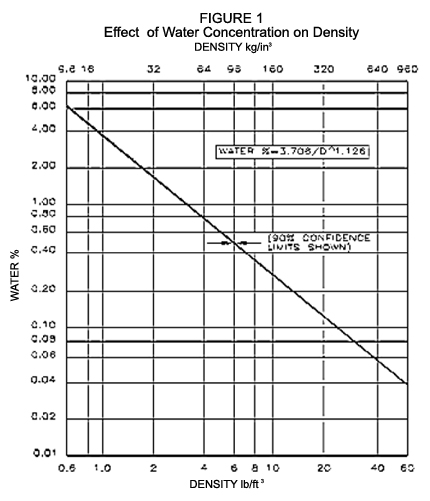
A common method used to obtain a change in load capacity is a change in density. At Piping Technology and Products, we offer 10 lbs. / ft3, 14 lbs. / ft3, and 20 lbs. / ft3 densities.

Density varies when the amount of blowing agent (water content) changes. The density of polyurethane decreases with increase in water content (See Fig. 1). This relationship can be shown as follows:

W = 3.706 / D1.126

Where: W = % of water content
D = Density of foam (lbs./ft3.)

In addition to density, the strength of a rigid urethane foam is also influenced by many factors such as catalyst, surfactant, type of mixing, the type of foaming system: base polyol and isocyanate, and the influence of each of these on the foam cell structure.
Rigid urethane foams generally have an elastic region in which stress is nearly proportional to strain. They do not exactly follow Hooke’s Law (stress is proportional to strain) because the curve is very slightly “S” shaped. Fig. 2 shows this in detail.

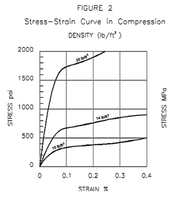
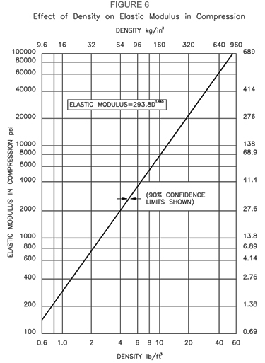
Polyurethane is anisotropic, or polyurethane is stronger in the direction of foam rise. At Piping Technology and Products, the anisotropic character or directional properties of our polyurethane is reduced by overloading the mold used to form the polyurethane. By overloading the mold, we can control the cell structure and provide uniform physical properties. A relationship between compressive strength and the density of the foam is given in Fig. 3.

Polyurethane is a thermosetting material; however, it does soften slightly with increased temperature and hardens somewhat at very low temperatures. Softening at high temperatures affects the polyurethane in two ways: (a) loss of strength properties and (b) change in foam dimensions (particularly low-density foams). Low temperatures generally have a very little effect on polyurethane properties other than to make them a little harder and more brittle. See Fig. 4 for these effects.

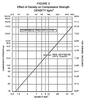
Rigid polyurethane foams have a relatively large amount of cross-linking as the foam expands. Our suppliers of the raw chemicals control the degree of cross-linking by functionality (higher functionality produces more cross-links) and molecular weight of the components in the blend. The rigid cells provide the poured foam with strength and the interior space provides low thermal conductivity. Water is used as the blowing agent for foam in this 10 to 40 lb. density range.

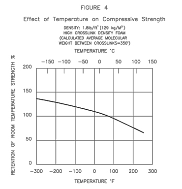
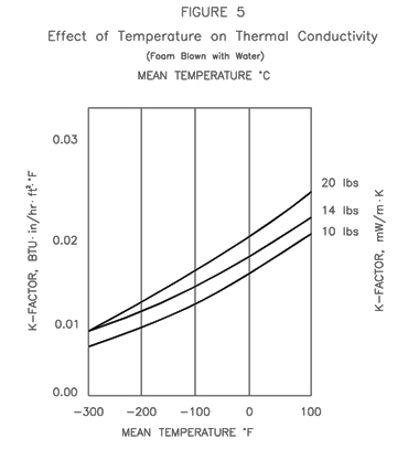
The relationship between temperature, thermal conductivity and the density of polyurethane foam is shown in Fig. 5.

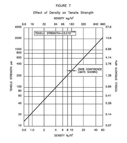
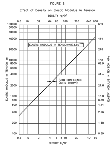
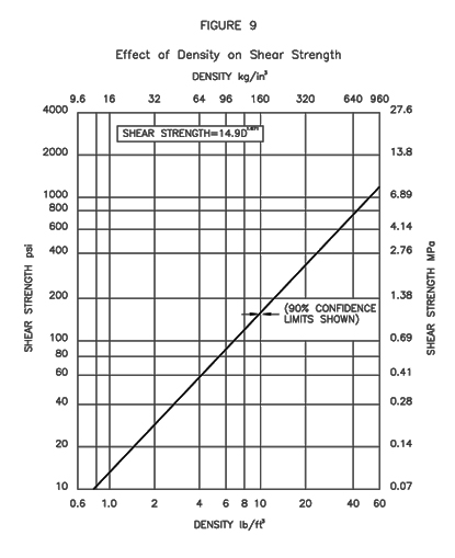
The relationships of foam’s density with its Elastic Modules in Compression, Tensile Strength, Elastic Modules in Tension, and Shear Strength are given in Figs. 6 through 9 respectively. Please see the following for the respective curves.

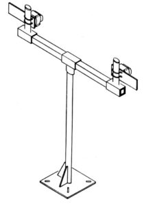
Piping Technology & Products has a complete manufacturing facility for production of polyurethane required for pipe supports. We invite our customers to visit our facility and observe the fabrication of insulated pipe supports of all types.

DENSITY
COMPRESSIVE STRENGTH
FLEXURAL STRENGTH (flatwise with gran) (psi)
TENSILE STRENGTH (with grain) (psi)
MODULUS OF ELASTICITY (psi)
CLOSED CELL CONTENT (%)
TEMPERATURE (F) CONTINUOUS OPERATION
K-FACTOR
THERMAL CONDUCTIVITY (btu/hr m^2 of)
SHEAR (flatwise 1/8″ thk. Psi)
DENSITY (lb/in^3)
WATER ABSORPTION (%)
PUF (10lb/cuft) 200.00 400.00 300.00 6,000.00 95.00 -300.00 0.08 0.1600 180.00 0.1157 0.22
PUF (14lb/cuft) 300.00 600.00 500.00 11,000.00 95.00 -300.00 0.12 0.2000 200.00 0.1736 0.18
PUF (20lb/cuft) 500.00 1,100.00 600.00 20,000.00 95.00 -300.00 0.14 0.2500 400.00 0.2893 0.13

Laminated Beechwood Technical Information

test service nolan

Laminated Beechwood Technical Information Permali® or Insulam® is an insulating material used in applications which require high tensile and compressive strength (see table below). In addition, due to its exceptional resistance to moisture, it serves as a suitable insulator where the support (flare lines & dummy legs) is exposed to harsh environmental elements. Permali® or Insulam® is a phenolic laminated (densified, impregnated wood) product made from carefully selected thin beechwood veneers. These wood layers are impregnated under vacuum conditions with a special synthetic resin and then densified through the application of heat and pressure. The result is a homogenous material that combines the great strength and toughness of wood fibers with the excellent stability and dielectric properties of the most advanced thermosetting. The phenolic laminated block material is furnished with cross-directional fibers as shown in Figure 10 below.

NOTE: Cross-laminated.
For components in compression or for parts stressed in more than one direction.
Sizes to suit most applications.


Density Permali
  Compressive Strength   30,000.00
  Flectual Strength (flatwise with grain) (psi)   15,000.00
  Tensile Strength (with grain) (psi)   15,000.00
  Modulus of Elasticity (psi)   2.0 x 10^6
  Closed Cell Content (%)   N/A
  Temperature(F)-Continuous Operation   221.00
  K-Factor   N/A
  Thermal Conductivity (btu/hr m^2 of)   0.0018
  Shear (flatwise) (1/8″ thick) (psi)   7200.00
  Density (lb/in^3)   0.0469
  Water Absorption (%)   0.75

Insulation Layering

test service nolan

At Piping Technology and Products, we recommend multiple layers for cold shoe supports that have a total insulation thickness of four inches or greater.

In the field, cold shoes are typically mated with existing line insulation. Due to the low temperature of the pipe, moisture from the ambient air can be drawn to the pipe through gaps that may exist between the cold shoe and the line insulation. At lower temperatures, where thicker insulation is required, there is greater opportunity for moisture to be drawn to the pipe. This is because of the increased single mating surface area between the line insulation and the cold shoe.

A solution that eliminates this potential problem is providing multiple mating surfaces between the line insulation and the pipe support. Hence: When insulation thickness is four inches and greater, multiple layers provide an improved moisture seal due to steps between the different layers.

To determine the thickness of each layer, refer to our suggested layering chart on the following page. To use this table, reference the total insulation thickness to determine how many layers are suggested and how thick each layer should be.

Example: A four inch (4″) pipe that requires five inches of insulation: Referring to PT&P’s suggested layering chart, two layers are required. The first layer (inner layer) thickness is suggested to be 2″ and the second layer (the outer layer) is suggested to be 2″ thick.

Piping Technology and Products can tailor a layering system to meet the customer’s requirements. The included layering chart is only a guideline.

NOMINAL
Insulation Thickness
Layer 1
Layer 2
Layer 3
1″
1″
1.5″
1.5″
2″
2″
2.5″
2.5″
3″
3″
3.5″
3.5″
4″
2″
2″
4.5″
2″
2.5″
5″
2.5″
2.5″
5.5″
2.5″
3″
6″
2.5″
3.5″
6.5″
2.5″
2″
2″
7″
2.5″
2.5″
2″
8″
3″
2.5″
2.5″

Top