Have a Look Through PT&P’s Newly Designed Website

test service nolan

Pipe Clamp Design, Application & Installation Webinar

test service nolan

Date: Thursday, May 3, 2018

Register for either time slot: 10:00 am OR 2:00 pm CDT

Note: Time Zone is CDT * Central Daylight Time / GMT -5h

Pipe clamp webinar thumbnail

This presentation will cover Pipe Clamps, including Hold-Down Clamps, Riser Clamps, Clevis Hangers, Yoke U-Bolt Clamps and Structural Supports. Learn how the appropriate type of pipe support is chosen based on the different design conditions. Find out how Finite Element Analysis is used in the design process and view the custom pipe supports designed for extreme applications.


After registering, you will receive a confirmation email containing information about joining the webinar.

Trunnions with Micarta ® G-10 Designed for a Cryogenic Pipeline

test service nolan

Trunnions Designed for a Cryogenic Pipeline at an LNG Facility

Type: Trunnions for Cryogenic Temperatures
Size: 8″-24″ Dia. | 12″-18″ L | 6″-15″ W | 6″-40″ H
Material: Micarta® G-10 Insulation | CS | SS
Design: Cryogenic Temperatures of -320°F
Testing: MTR’s | Non Destriuctive (PMI) | Q.C.

PT&P custom designed trunnions for a cryogenic pipeline at an LNG facility in Australia. The insulated supports were fabricated with carbon steel base plates, 304L stainless steel plates and fasteners. To prevent cryogenic temperatures of -320°F from transferring to the base of the trunnion support, Micarta® G-10 was used as insulator. The trunnions were designed to support pipe sizes from 8”-24” with dimensions ranging from 12”-18” in length, 6”-15” in width and 6”-40” in height. MTR’s were provided, and non-destructive testing (PMI) was preformed, along with standard Q.C. inspection prior to shipment.

This type of support is available in pipe sizes between 1/2″ to 42″ NPS; however, PT&P can customize any size needed. The standard material for these supports are galvanized or hot-dipped galvanized carbon steel. These supports were customized with Micarta® instead of the standard high density polyurethane with vapor barrier. When ordering, specify pipe size, insulation thickness and length. See more on Figure CS-6030 from our cryogenic pipe supports section.

Piping Technology & Products and Pipe Shields have been a major international supplier of pipe shoes and pre-insulated supports for more than 10 years. Our cryogenic pipe supports comply with the following standards ANSI / ASME B31.1 & B31.3 and The Manufacturers Standardization Society SP-58, 69, & 89.

Cryogenic Pipe Supports with Micarta® G-10 for an LNG Facility in Australia

test service nolan

Cryogenic Pipe Supports with Micarta® G-10 for an LNG Facility in Australia

Type: Cryogenic Pipe Supports
Size: Pipe Size of 1” to 36”
Material: LTCS Material Tops, Stainless Steel, & Micarta® G-10 Insulation
Design: -50°F
Testing: PMI

Piping Technology and Products supplied these cryogenic and axial stop cold shoes for an LNG facility in Australia. The cryogenic pipe supports were fabricated with LTCS material tops, stainless steel and Micarta® G-10 insulation blocks. They were a wide range of lengths from pipe size of 1” to 36”. The cryogenic temperatures are low as -50°F. A special paint system was used for the carbon steel components to resist rust. PMI testing was performed on the stainless parts prior to the 4-6 week shipping.

Cryogenic Pipe Supports with Micarta® G-10 for an LNG Facility in Australia

test service nolan

Cryogenic Pipe Supports with Micarta® G-10 for an LNG Facility in Australia

Type: Cryogenic Pipe Supports
Size: Pipe Size of 1” to 36”
Material: LTCS Material Tops, Stainless Steel, & Micarta® G-10 Insulation
Design: -50°F
Testing: PMI

Piping Technology and Products supplied cryogenic pipe supports with axial stops for an LNG facility in Australia. The cold shoes were fabricated utilizing low temperature carbon steel, stainless steel and Micarta® G-10 insulation blocks. We supplied a wide range of lengths and pipe sizes from 1” to 36”. The cryogenic temperatures are low as -50°F. A special paint system was used for the low temperature carbon steel components to resist rust. PMI testing was performed on the stainless parts. Delivery was within 4-6 weeks.

Insulated Shoe Designs

test service nolan

Download PDF

Fig. 4500 – HOT SHOE DESIGN
(MARINITE®️/CALCIUM SILICATE)

Fig. 4600 – COLD SHOE DESIGN
(POLYURETHANE)

Fig. 4700 – COLD SHOE DESIGN
(PERMALI®️/MICARTA®️)

Fig. 4800 – COLD SHOE DESIGN
(G10)

SIZE RANGE: For use with 1/2” through 72”, most designs. Insulation thicknesses of 1”, 1 1/2”, 2”, 2 1/2”, 3”, 3 1/2”, 4”, and larger sizes where specified.

HOW TO SIZE: Refer to “Insulation Chart”, on the next page for sizing the insulation material.

ORDERING:
Specify figure number, pipe size, insulation thickness, and insulating material.

Example:

PTP-4700-4-3-B
• 4700 = Type of insulated shoe (cold)
• 4 = Nominal pipe size
• 3 = Insulation thickness
• B = Insulating material (micarta®)

Piping Technology & Products Slide Bearing Plates Slideshow

test service nolan

Engineered Spring Supports General Information

test service nolan

Download PDF

Piping Technology & Products, Inc. is a manufacturer and fabricator of all types of pipe supports. This section is devoted to variable spring and constant supports. In addition to the many standard supports you will find described here, we will design and custom-build special supports to meet your specific needs. In fact, many of the items you will see in this catalog were developed for the specific requirements of a customer who could not use the standard designs available in our industry. If you do not find what you need, or if you need technical advice, please contact us.

Designers of piping systems must provide for the pull of gravity and for movement due to thermal expansion. Spring supports, variables, and constants are devices which are cost-effective and structurally sound in solving certain pipe support problems. Constants are more expensive, so they are usually used in more critical applications, described in detail in the Constant Spring Hangers section.

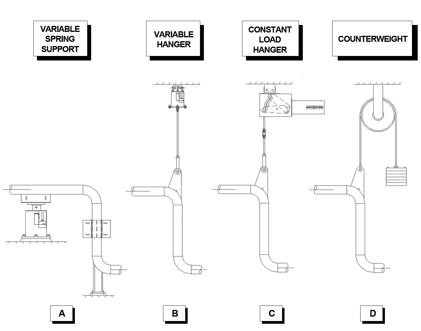
The illustration below shows three applications of spring supports and one involving a counterweight. In figure (A), a variable spring support is placed under the horizontal pipe just left of a vertical section which has a guide and rigid support. In (B) a variable hanger is suspended from above and connected to the elbow above the vertical section. In (C) the designer has chosen a constant load hanger because the vertical section is connected to a critical nozzle. A counterweight such as shown in (D) may be useful when pipe weights are unknown and must be balanced in the field. Piping Technology & Products, Inc. will calculate and custom-fabricate such counterweights for you.

Engineered spring supports configurations

Top