High-Temperature Pre-Insulated Pipe Support for a Chemical Plant

test service nolan

Custom High-Temperature Pre-Insulated Pipe Support for a Chemical Plant

This custom-designed insulated pipe support will be used for a high-temperature pipeline at a chemical plant in Canada. This hot shoe was customized without the U-base and modified with an extended length. It will be used to prevent the movement of a 6″ diameter pipe in the axial direction. Axial stops will be welded to the clamp O.D. in the field. The plates are 11-5/8″ O.D. x 48″ in length and fabricated from A36 carbon steel. The insulation is 2″ thick high-density calcium silicate and well-suited for temperatures up to 1200°F. A hot shoe is a pipe support that can be used for high-temperature applications, such as high-pressure steam lines or boiler feed water, where heat loss through the pipe support is not desirable. Insulated hot shoes can be designed and used for temperatures up to 1400° Fahrenheit.

PT&P REF. ORIGINAL POST 06022021

Furnace Applications – Spring Supports, Expansion Joints & Furnace Seal Bags

test service nolan

Ptp furnace application products

An industrial furnace, also known as a direct heater or a direct-fired heater, is a device used to provide heat for an industrial process. Furnace designs vary as to their function, heating duty, type of fuel, and method of introducing combustion air. Heat is generated by an industrial furnace by mixing fuel with air or oxygen, or from electrical energy. The residual heat will exit the furnace as flue gas. Types of industrial furnaces include batch ovens, vacuum furnaces, and solar furnaces. Industrial furnaces are used in applications such as chemical reactions, cremation, oil refining, glasswork, metallurgy, mechanical engineering, chemicals, ceramic, and building materials. Industrial furnaces using fossil fuels are characterized by heat losses from flue gases with a temperature of 500°C and above.

PT&P supplies many products that are well-suited for furnace applications. The first category we’ll take a look at is engineered spring supports. We size furnace springs the same way as we would for a conventional variable or constant spring support. Construction may include a welded design instead of bolted and custom nameplates with the test data and ID tag. Most furnace spring supports are coated with red oxide primer to avoid potential hazards when exposed to high temperatures.

Ptp furnace application variables in service combined

PT&P specially designed and fabricated hundreds of altered Type-A variable spring hangers in order to accommodate the special travel and spring rate needed to support the furnace tubes of a hydrogen reformer in Venezuela. To accommodate customer-specified travel and spring rates, modified spring coils were required. With a travel of 8-7/8″, the variable spring hanger casing lengths were increased from the standard size of 32″ to over 6′ long. The calculated spring rate is 79 lb/sq in for an operating load of 2,804 lb. and an installed load of 3,505 lb. The housings are coated with heat-resistant paint, which protects the spring coils from corrosion and high temperatures in the furnace area.

Expansion joints are not installed inside furnaces due to the extremely high temperatures of the environment and the piping system. Expansion joints will typically be found on the ductwork and in the piping coming in and out of the furnace. In the last six months, we have shipped over 40% of our expansion joint jobs in less than 2 weeks to meet customer project deliverables.
Fabric expansion joint application

Fabric expansion joints that are in-service near furnaces, typically include a 3-layer belt consisting of silicone, fiberglass, PTFE, and mineral wool insulation. The configurations are either round, rectangular or square as seen in the examples below.

Ptp furnace application products

Furnace bags are used to seal high-temperature tubes that penetrate the furnace floor. The furnace bag consists of multiple layers of flexible, flame and heat-resistant, impervious fabric designed to operate from start-up to high-temperature design conditions. The bag will expand and contract with the varying furnace temperatures.

Furnace Bag

Stainless steel clamps or band straps connect one end of the pipe that goes through the penetration opening and the other to another sleeve in the furnace floor. A tapered steel coil is installed around the conduit inside the bag to prevent the fabric from collapsing inward during vacuum conditions. PT&P’s standard furnace seal bag is nickel reinforced, with a special coating that reduces airborne fibers and increases tensile strength.


Furnace application diagram

PT&P REF. ORIGINAL POST 11092021

PT&P Manufactures and Installs an 85 ft. Pipe Rack and Pipe Spools

test service nolan

PT&P supplied “on-time delivery” of two industrial structural steel pipe racks and the accompanying pipe spools that would be attached to storage tanks measuring approximately 120 ft. in diameter and over 85 ft. tall. Pre-engineered pipe racks attached to storage tanks are used in a wide range of industries from waste water treatments plants, community water storage tanks, to above ground storage tanks used in refineries, natural gas, and petrochemical plants.

PT&P leveraged its breadth of manufacturing and engineering capabilities to reduce costs for its client in the deployment of this pipe rack. Our focus was to complete as much work as possible in our production facility, where costs are typically far lower than in the field. We made adjustments to the design to aid in-field deployment to minimize total overall costs. This project also leveraged our capabilities with structural steel, pipe spools, TPI, and insulation. We have all of these capabilities in-house, which made it easy to fabricate the complex structures in this project.

Each pipe rack had an overall dimension of 12 ft. wide and 113 ft. tall and was fabricated from carbon steel. Due to the overall length, each frame was fabricated in two sections in our shop in order to transport each to the job site. Additionally, each frame was provided with lifting lugs designed by PT&P to facilitate both, the transporting of each frame half-section and the subsequent vertical lift of each completed unit. Each pipe rack was fitted with 9 pipe spools ranging in diameter from 2″ to 12″ (6 were insulated pipe spools, and 3 were non-insulated pipe spools). The pipe material used to fabricate the pipe spools were SA-53, SA-106, and SA-333.

Six of the pipe spools were supplied pre-insulated. At the ends of each section of the pipe spool, there were bare sections of pipe where PT&P field services would later perform “tie-in welds” in the field.

Ptp pipe racks large tank installation 181868 500pxw

After completing shop fabrication, the pipe racks were prepared to be transported to the job site location for final assembly before installation by PT&P field services. This consisted of bolting the two halves of the pipe rack together and completing the “tie-in welds” at each pipe spool connection. All of the “tie-in welds” were examined and verified by X-ray analysis. After completion of all the “tie-in welds”, PT&P Insulation Department installed insulation in the field on the 6 pipe spools requiring insulation at these connection points.

Ptp rod hangers 181868
Rigid Rod Hangers

Each section of the pipe spool was supported from the top of the rack by a rigid rod hanger also supplied by PT&P. Rod hanger assemblies are round steel bars normally threaded and used to connect other components, such as pipe support hardware, to make a pipe hanger assembly. PT&P’s field service team installed the main pipe rack with seven pipe spools each over 86 ft. long on large storage tanks. The pipe spools were positioned on the pipe rack steel using special U-bolts to “guide” the piping.

U-bolts are u-shaped rods with threaded ends that fit around a pipe and are attached to a supporting member. These U-bolts were coated in plastic to prevent corrosion between the pipe and the U-bolt material. Additionally, thermoplastic isolators (TPI) were also used to prevent corrosion between the pipe rack steel and the pipe spools. TPI can be customized in height, width, length of TPI, hole sizes, hole locations, and special shapes.

TPI Pipe
U-Bolt with TPI
Frp wear pads 143770
FRP Wear Pads

Also installed on the insulated pipe spools were FRP wear pads that rested on the thermoplastic Isolator. FRP is also known as non-metallic wear pads, which are used for corrosion protection for uninsulated piping systems to extend the life of the pipe.

Ptp pipe racks large tank installation layout 600px

After assembly by the PT&P field services, each complete unit was lifted vertically into position and bolted to the storage tank at the “tank connection points.” This demonstrates our ability to provide rare expertise in all facets of project management including planning, engineering design, logistics, and job site management.

We have a fully diversified operation that is customizable based on your unique needs. If you just need stock supports and standard items, we can provide them very quickly. Our engineering team can help find the best support(s) for your application. Or our field service team can inspect your pipeline conditions and recommend the best solutions. Our team also regularly completes installations and conducts on-site project management. We are your one-stop shop for pipe supports, insulated supports, expansion joints, vibration solutions, pipe stress analysis, and more.

PT&P REF. ORIGINAL POST 05182021

Over 1/2 a Million Instrument Stands for LNG Service and Operator

test service nolan

Over 1/2 a Million Instrument Stands for LNG Service and Operator

Floor mount support modules utilize a 1/4″ steel base plate to clamp, bolt, or weld instrument assemblies directly to a wall or beam. These primary modules can be used independently or together with secondary modules to construct a universal support package for any instrument in any position. These units were furnished with a hot-dipped galvanized finish to protect against corrosion. We can also provide other finishes such as painted or powder-coated. Instrument stands are used in almost any plant that utilizes process instrumentation such as flow meters, pressure, and temperature sensors, and other instruments used to monitor processes both onshore and offshore. PT&P also offers a complete line of adjustable instrument support components which, when combined, will create various configurations to your exact requirements or individual needs. In addition, we can also provide customized instrument supports fabricated from 304 SS or other materials according to your company’s specifications. We have supplied instrument stands for coker units, LNG, and refinery facilities. For additional information about our instrument support stands, please click on the following link: PT&P Instrument Supports Catalog

In these times of supply chain considerations and challenges on major projects, we’ve consistently been the best partner to ensure timely design, production, and delivery of project needs on any scale with the largest range of products and services throughout your piping systems. Along with being a proven supplier on multi-billion dollar projects, we also work hand in hand with single-plant turnaround needs every day.

PT&P REF. ORIGINAL POST 08182020

Constant Spring Supports with Stainless Steel & Graphite Slide Plates

test service nolan

U-Type Constant Spring Supports in Texas

Type: Constant Spring Supports
Size: 35-7/16″ Height & 75-3/4″ Length
Material: A36 Carbon Steel with HDG | 304 Stainless Steel
Design: 9″ Total Travel at 979°F | Operating Load 6,183 lb.
Testing: Hydro tested at 6,744 lb.

These 200 U-Type constant spring supports with slide plates were designed by PT&P for a plant in Texas. They are fabricated from A36 carbon steel with an HDG finish and are typically designed for vertical movement only. However, when there is lateral or axial movement in the piping system, slide plates can be used in conjunction with these constants. In this instance, graphite slide plates are bolted to the constant’s load flange and used with an upper slide plate manufactured from 304 stainless steel with a mirror finish. The upper slide plate can be welded to the base of a pipe shoe, trunnion, or the saddle of a pressure vessel. Each of the constant spring dimensions are 35-7/16″ in height and 75-3/4″ in length. They are designed for a piping system with 9″ of total travel at 979°F and an operating load of 6,183 lb. Each of these units were load tested to meet the hydro test load of 6,744 lb. before shipment.

Products such as these are used in many different kinds of plants all over the world including refineries, renewable diesel plants, chemical plants for operations such as propane/propylene splitter units, and power plants. We have the ability to custom design and manufacture constants for specific loads and various environmental conditions. A point to note, we provided similar constant spring supports supporting loads over 150,000 lb. for crude oil processing at one of the largest refineries in the world just last year (view this project). Petroleum refineries change crude oil into products such as jet fuel, gasoline, polypropylene, polyethylene, propane, sulfur, carbon black feed, and diesel that can be used for transportation, heating, feedstocks for making other chemicals, generating electricity, renewable energy, and paving roads. Constants use a spring coil (or series of coils) to accommodate pipe movement from the initial (installed) condition to the final (operating) condition of the piping system. For all constant spring supports there is no difference in load and the supported load will remain uniform throughout the deflection cycle. Learn more about constant spring supports


PT&P REF. ORIGINAL POST 01122018

B-Type Variable Spring Hangers for an overseas LNG Facility

test service nolan

B-Type Variable Spring Hangers for an LNG Facility in Texas

Type: B-Type Variable Spring Support Assemblies
Size: 13″ to 120″ range pipe elevation
Design: Operating Loads: 9,320 lb. to 28,2000 lb.
Spring Rates 4,700 lb./in. & 5,320 lb./in
Material: | Hot-dipped Galvanized Carbon Steel
Testing: Load & Travel Test |  Q.C. Inspection

These variables were supplied to an overseas LNG facility where accessibility is limited due to the remote location in the facility as well as the plant itself. Products shipped must be very dependable and long-lasting because of the difficulty of shipping to this location. Variables use coiled springs to support a load and allow movement. The resistance of the coil to a load change during compression, which is why these devices are called “variables”. We offer a variety of different designs of variable spring pipe supports. PT&P with its long-standing history and experience has set up optimized manufacturing to offer an unparalleled set of customization options with minimal impact on delivery timeframes to support JIT deliveries and help manage cash flows on such large capital-intensive projects. In addition to our standard (hot-dipped galvanized, neoprene coated spring coils) variable spring supports, we can customize our springs to accommodate special materials, finish, dimension, load, load adjustment, travel, and travel stops, as well as provide sensors for remote monitoring.

Given the shift in global LNG production due to volatile political situations outside the US, the US has become the largest exporter of LNG this year globally. US LNG exports will continue to grow because of increased LNG export capacity, increased international natural gas and LNG prices, and increased global demand, especially in Europe.

During the initial build out in LNG globally in the late 1990s/early 2000s, PTP provided the platform to its customers and their clients for extensive innovation concerning all phases of development concerning pipe supports for LNG plants and terminals starting with product design, testing, material, and climate considerations. As the “thought leaders” in product design, we helped develop and produce the now most commonly used cryogenic supports utilizing G-10 insulation. As LNG capital projects return to the US, you can count on PTP to provide an unparalleled track record and expertise to move your LNG projects along safely in a timely cost-effective manner to meet world energy needs.

PT&P REF. ORIGINAL POST 04072020

Sway Strut & 3-Bolt Pipe Clamp Assemblies

test service nolan


Sway Strut & 3-Bolt Pipe Clamp Assemblies Designed for a Power Plant in California

Type: Sway Strut & 3-Bolt Pipe Clamp Assembly
Size: 30″ NPS | 44-1/8″ CC | 4″ Adjustment
Material: Carbon Steel | 304 Stainless Steel
Design: Restrain Tensile/Compressive Force in 1 Direction
Permit Movement in Other Directions

PT&P fabricated and designed sway strut and 3-bolt pipe clamp assemblies for a power plant in California. Supplied to a natural gas-fired, combined-cycle facility, the plant will produce over 620-megawatts of power and help to repower older generating infrastructure with more environmentally friendly technology. The assemblies are manufactured from carbon steel with 304 stainless steel load pins. They are designed for a 30″ diameter pipe. This sway strut has a pin to pin length of 44–1/8″ and comes with a standard 4″ adjustment. The sway struts are designed to restrain either tensile or compressive force in one direction while providing for movement due to thermal expansion or contraction in other directions.View Product.

PT&P REF. ORIGINAL POST 08132019

Sway Struts Designed for an LNG Liquefaction and Export Facility

test service nolan

Sway Struts Designed for an LNG Liquefaction and Export Facility

Piping Technology & Products is a manufacturer of all types of pipe supports to areas all over the world ranging from sports stadiums to geothermal to infrastructure applications. In fact, many of the items you will see on our website were developed for the specific requirements of a customer who could not use the standard designs available in our industry. These sway strut assemblies were designed and fabricated for a large LNG liquefaction and export plant. Sway struts are used in a wide range of applications in power plants, chemical and refineries to restrain movement in tension (or X plane) while allowing lateral movement (in the Y and Z plane). These fig. 2100F, size C sway struts are designed with 4” adjustment for loads up to 4,500 lb. The pins are fabricated from a high alloy steel for added strength and the threaded rod ends are carbon steel and hot-dipped galvanized. The sway strut body was hot-dipped galvanized after the donut and pipe were welded. The rod ends and end brackets were galvanized a second time for added corrosion resistance after the holes for the IKO bearings and pins are enlarged to fit these component parts. The C-C dimension is 30-11/16” and a quality control inspection involving thread engagement was completed prior to shipment. Piping Technology and Products is a manufacturer of all types of pipe supports to areas all over the world ranging from sports stadiums to geothermal to infrastructure applications. In fact, many of the items you will see on our website were developed for the specific requirements of a customer who could not use the standard designs available in our industry. If you do not find what you need, or if you need technical advice, please contact us.

PT&P REF. ORIGINAL POST 06222021

Constant Spring Supports for Heat Recovery Steam Generators (HRSG)

test service nolan

Custom Constant Spring Supports for Heat Recovery Steam Generators

PT&P custom-designed constant spring support assemblies for a heat recovery steam generator at a combined-cycle power plant. These power plants utilize gas turbines, steam turbines, heat exchangers along with other components to make use of “exhaust waste” for a more efficient system. These 200-F Type constants were fabricated from A36 carbon steel and include a hot-dipped galvanized finish. The spring coils are formed from alloy steel and are neoprene coated. They are designed for an operating load of up to 886 lb., and up to 6″ of maximum travel. They are designed to be placed beneath the unit being supported and allow for movement in the vertical direction (up or down). The dimensions are 13″ W x 31″ L x 18-1/2″ H. Standard load and travel tests along with a quality control inspection were conducted prior to shipment. Since the mid-1970s, we have been working with power plants and have deep expertise in the evolution of power plant design over the last 40+ years, including the impact that it has had on Pipe Stress Engineering requirements. We have supplied products and services for a wide variety of power plants including Coal, Natural Gas, Biomass, Solar, Wind, Geothermal, Nuclear, and Hydroelectric. As the only major Global Provider of Expansion Joints, Engineered Pipe Supports, and Pipe Stress Engineering, we have the ability to provide unique solutions and solve the most challenging scenarios that may arise.

PT&P REF. ORIGINAL POST 01062021

Pig Launchers and Receivers Custom Designed for a Chemical Plant

test service nolan


Pig Launchers and Receivers Custom Designed for a Chemical Plant

Type: Pig Launchers & Receivers
Size: 4-14” Diameter | 72-98″ Long | 48″ Tall Stands
Material: 316 L SS | SA 106-B | SA-105
Design: Operating Temperature: 221°F
Operating Pressure of 117, up to 205 PSI

PT&P‘s Sweco Fab division custom designed and manufactured pig launchers and receivers for a chemical plant in Saudi Arabia. A pig launcher is a pressurized container used to shoot a cleaning device (called a "pig") through the pipeline to perform a variety of functions including cleaning, monitoring, and maintenance of the pipe. Pig launchers & Receivers are used in a variety of industries such as oil and gas, paint manufacturing, food processing, and in cross-country pipelines. The main advantages of pipeline pigs are inspection and cleaning which can be conducted without disrupting line contents, shutting down pipeline flow, and helping to prevent cross-contamination saving both money and time for plant operations as well as maintenance teams. These units are fabricated from stainless steel 316 L, SA 106-B, and SA -105. Dimensions for these pig launchers and receivers are 4", 6", 8", 10", and 14" in diameter and range from 72" to 98" long. They are mounted on 48" tall stands. They are designed for an operating temperature of 221°F with an operating pressure of 117, up to 205 PSI. You can also skip the line and order on Amazon any of our other Standard Expansion Joints and Pipe Support Components

PT&P REF. ORIGINAL POST 09252019

Standard Pipe Support Components Available on Amazon

test service nolan

Need a standard product quickly? Or know what you need and don’t need a quote? Skip the line and order through Amazon. From forged carbon steel turnbuckles and light or heavy 2-bolt, 3-bolt pipe clamps, riser clamps to long tangent u-bolts, we stock standard sizes for your quick-turn orders.

*If you need assistance, we are always available 24×7 via our emergency service or just send an email to info@pipingtech.com.


Ptp fig30 forgedcsturnbuckle
Fig. 30 Forged Carbon Steel Turnbuckle
Ptp fig60 heavy 2 bolt pipe clamp
Fig. 60 Heavy Two-Bolt Pipe Clamp
Ptp fig70 light 3 bolt pipe clamp
Fig. 70 Light Three-Bolt Pipe Clamp
Ptp fig80 heavy 3 bolt pipe clamp
Fig. 80 Heavy Three-Bolt Pipe Clamp
Ptp fig90 riser clamp
Fig. 90 Riser Clamp
Ptp fig100 long tangent u bolt
Fig. 100 Long Tangent U-Bolt
Ptp fig90 riser clamp
Piping Technology & Products, Inc. Expansion Joint (85 PSI)
Ptp fig100 long tangent u bolt
Piping Technology & Products, Inc. Expansion Joint (150 PSI)
Ptp fig90 riser clamp
Piping Technology & Products, Inc. Expansion Joint (300 PSI)

Constant Spring Supports

test service nolan


Piping Technology & Products’ constant spring hanger, usually referred to as a constant, provides constant support force for pipes and equipment subjected to vertical movement due to thermal expansion at locations where maintaining a constant stress is critical. This constant resistance is achieved by having two-moment arms pivoted about a common point. The load is suspended from one of these arms, and a spring is attached to the other. With an appropriate choice of moment arms and spring properties, a resisting force can be provided that is nearly independent of position. As with variable springs, Type refers to the connection of the constant to the structure and the pipe. Figure 4 shows the attachment for Types A – E. The designation Figure 100 and 200 refer to the orientation of the spring can. This is vertical for Figure 100, and horizontal for Figure 200.

Travel stops are installed in all constants before shipping. These must be present during installation and any hydro testing, but must be removed before normal operations. They are usually pins, but in some cases may be keys. See note below on travel key removal. In either case, the load must be adjusted so that the travel stop is easily removed.

Caution: Do not force the travel stops.

constants

Figure 4: Constant Hangers Types A – E.


Red, White and Blue Marks:

All constants are shipped with at least 3 color-coded rivets (red, white and blue).
Red: operating (HOT) position
White: installation (COLD) position
Blue: over travel (MAX AVAILABLE) position

Below are sketches of one direction vertical travel:


Below is a sketch of dual direction vertical travel:
constants

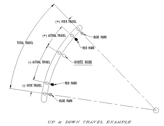
Types A – E Constants (100 & 200)

travel stop position

Figure 5: Travel stop position.

1. Secure the hanger to a structure capable of handling the operating load, at a point where the constant’s load coupling is directly over the desired point of attachment to the pipe in the operating position.
2. The hanger rod and loading arm of the constant should be unobstructed.
3. Attach the connecting rod to the turnbuckle with full thread engagement.
4. Transfer the load by turning on the turnbuckle before removing the travel stop.
5. If required, hydro testing should be done at this time.
6. Once the load is transferred, the travel stop must be removed. The travel stop (painted red) should now slip out easily. If not, refer to Figure 5. The travel stop pin must be moved to the center of its hole by adjusting the hanger load. The hanger load needs to be increased if the pin is in position A, or decreased if the pin is in position C. Once disengaged, the travel stop may be stored by hanging it from the constant.
7. The hanger load should now be readjusted to the cold (white mark) position.
8. When the operating conditions are reached, check the hanger to assure the indicator is at the hot (red mark) position.

Type F – 100 Constants

F-Type Constant and Travel Stop Pin Positions

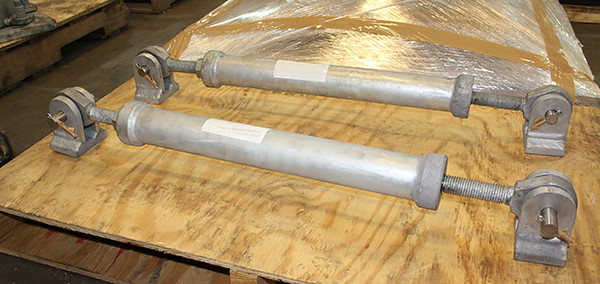
Figure 6: F – 200 Type constant, and Travel Stop Pin positions.

1. Secure base plate to the structure.
2. If the constant is of the platform type (see Fig. 6), place the pipe on the platform, and attach it to the platform. If there is no platform, attach a strut to the piping, then to the constant support.
3. Hydro test line if necessary.
4. The travel stop should be in the middle of its hole. If the travel stop is in the A- configuration (see Fig. 5), contract the strut, and if it is in the C- configuration, expand the strut to force the travel stop pin to move to the center of the travel stop hole. When the travel stop pin is centered in the travel stop holes, it can be easily removed and the constant is ready for operation.

Danger!! If pin cannot be easily removed after struts adjustment, do not drive pin out.

Type 200 – F

The Type 200 – F constants are shipped with two installation rods.
1. Attach the base plate of the constant to the supporting structure by placing the constant in its installation location. If the clearance is tight, temporarily force the table down by loosening the 2 travel stop nuts on top of the angles, then tightening the nuts below.
2. Loosen the travel stop nuts below the angles to allow the load flange to rise up to the installed height: 3/8″ max. If the clearance is bigger than 3/8″, shim or grout the constant or pipe attachment accordingly. Re-tighten the 2 travel stop nuts above the angles.
3. Hydro test line if necessary.
4. Loosen and raise up the travel stop nuts above the angles at least a nut thickness to allow the removal of the travel stop rods. Remove the travel stop rods from the load table and store for future use. The constant effort support is now ready for operation.
200-F Type Constant

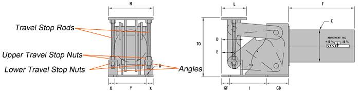
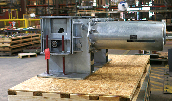
  Figure 7: Type 200 – F

Type 200 – U (Upthrust) Constants

200-U Type Constant

Figure 8: 200-U Type Constant, and Travel Stop Location
1. Attach the base plate of the constant to the supporting structure by placing the constant in its installation location. If the clearance is tight, temporarily force the table down by loosening the four lower travel stop nuts, then tightening the four upper travel stop nuts.
2. Loosen the upper travel stop nuts to allow the load flange to rise up to the installed height: 3/8″ max. If the clearance is bigger than 3/8″, shim or grout the constant or pipe attachment accordingly. Re-tighten the four lower travel stop nuts.
3. Hydro test line if necessary.
4. Back the four lower travel stop nuts all the way down. Back the four upper travel stop nuts all the way up, but do not remove from installation rods. The constant effort support is now ready for operation.

Type G Constant
The Type G constant consists of two Type 100 constants connected by a beam, with the pipe being supported on the beam.
1. Support the pipe at the desired elevation.
2. Attach load rods to the structural support.
3. Attach the constant to the load rods using the turnbuckles provided.
4. Using the turnbuckles, level the pair of channels connecting the two constants.
5. Keeping the channels level, transfer the pipe load to the constant, either by raising the constants or removing any temporary support for the pipe.
6. If hydro testing is required, this should be done now.
7. Remove the travel stops. If they are not in the center of their holes, use the turnbuckles to adjust the load so that the stops are in the center. They should be easily removed. If not, adjust the load until they are. Do not drive them out.
8. Using the turnbuckles, adjust the load indicator to the cold position.
9. After the load reaches normal operating conditions, check to see that the load indicator is at the hot position. If not, adjust with the turnbuckles.

G Type constant

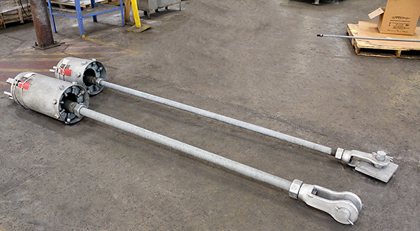
Figure 9: G Type Constant

MAINTENANCE INSTRUCTIONS 

  1. Each pipe support should be inspected periodically anywhere from monthly to annually (based on the surrounding environment) to verify load and movement with respect to the design load and travel on the nameplate on the constant frame. 
  2. Clean any and all dust and soot that may gather up in the coil housing especially in dusty environments (desert areas, windy location, and around coker units). 
  3. Remove any and all foreign objects and debris (bird nest, fallen objects, and pushed aside objects) that may impair spring coil, hanger rod, or load table movement. 
  4. On base type units, ensure the slide plate’s functionality through the absence/removal of dust, soot, and debris on the slide plates that exist between the load flange and the beam/pipe above it. 
  5. No greasing or lubrication is required to any of the constant support parts

Field Instructions for Load Adjustment, Fig. 100 & 200
Under no circumstances should an attempt be made to remove the lock nut and the load adjustment nut from the constant spring hanger.

Every constant spring hanger is calibrated in the factory and set to the load specified on the nameplate. Load adjustment in the field is discouraged as it may significantly change the system.

However, to provide for situations where the supported load is different from the calculated load, the constant spring hangers are equipped with load adjustment capability. The load adjustment capability consists of a load adjustment scale and indicator, which are used to increase (Figure 10A) or decrease (Figure 10C), the load by 10%. Thus, a 2000-pound hanger can be adjusted for loads from 1800 to 2200 pounds. The travel stop pin must be engaged before load adjustment is performed. Adjusting the load to higher or lower load from the load specified on the nameplate using load adjustment is approximate and not recommended.

Figure 10: Field adjustment for load. The Load Adjustment Scale is located on the spring can, near the adjustment nut.
To increase the cold setting, be sure that the travel stop pin is in place. Then loosen the lock nut at the end of the spring. Tighten the main nut, then retighten the lock nut.

To decrease the cold setting, be sure that the travel stop pin is in place. Then loosen the lock nut at the end of the spring. Loosen the main nut, then retighten the lock nut.

Constant Hangers with Adjustable Travel Stop Keys: Removal of Travel Stop Key

Adjustable Travel Stop Keys

Figure 11: Adjustable Travel Stop Keys

1. After hanger installation, remove the travel stop hex nuts from both sides. Check whether A-face or B-face of the threaded bolt is in constant with the travel stop keyhole as illustrated in Fig 11, above.
2. If the B-face of threaded bolt is in contact with the travel stop keyhole as shown in Figure 11, turn the turnbuckle clockwise. The travel stop bolt will move towards the center. At this point, the load has been transferred and the constant hanger is balanced with the pipe weight. The travel stop key can be easily removed.
3. If the A-face of threaded bolt is in contact with the travel stop keyhole as shown in Figure 11, turn the turnbuckle counterclockwise. The travel stop bolt will move towards the center. At this point, the load has been transferred and the constant hanger is balanced with the pipe weight. The travel stop key can be easily removed.

Custom Designed Pipe Shoes for a Facility in Louisiana

test service nolan


Custom Designed Pipe Shoes for a Facility in Louisiana


Type: Pipe Shoes
Size: 20” x 20”x 12”
Material: A 516 Gr. 20 Carbon Steel | 304 Stainless Steel
Testing: Standard Q.C. Inspection

Pipe shoes and pipe guides are available in a variety of designs. Slide plates may be included on the pipe shoes for smooth sliding. Custom pipe shoes and anchors can be designed to meet your specific design requirements. We can design pipe supports, such as these, for use on pipelines containing expansion joints or other critical components where lateral and vertical pipe movement needs to be controlled. Similar to this design, we can also manufacture pipe supports such as spider guides (our PT&P Fig.6) that are used adjacent expansion joints in order to avoid a fulcrum that could impose lateral and vertical deflection on critical components such as pumps, compressors, and turbines often used in various green energy plants such as nuclear, geothermal, solar, biomass and hydropower. The guides of the spider guide can be furnished with split sleeves for easy installation or solid, and they can be modified to suit special applications.

PT&P custom-designed and fabricated multiple pipe shoes for a general industrial contractor in Louisiana. The base of the pipe shoes are fabricated utilizing low-temperature carbon steel A516 Gr. 70, and the clamps are fabricated from 304 stainless steel. The pipe shoes provide rigid support to the pipeline in the vertical and lateral directions while allowing axial movement. The dimensions are 20″ x 20″x 12″.

PT&P REF. ORIGINAL POST 10102019

Custom Designed Constant Spring Supports for a Chemical Plant in Singapore

test service nolan

Custom Designed Constant Spring Supports for a Chemical Plant in Singapore

Type: Constant Spring Supports
Size: 15-¼” W x 17″ H x 46″ L with 9-¼” OD
Material: Carbon Steel | Hot-dipped Galvanized
Design: 2,379 lb. Load | 10″ Upward Movement

PT&P custom designed and manufactured constant spring supports for a chemical plant in Singapore. The constants are fabricated from A36 carbon steel and include alloy coil springs. The dimensions are 15-¼” W x 17″ H x 46″ L with 9-¼” OD. They were designed for an operating load of 2,379 lb. and movement of 10” upward and were specially designed to incorporate “telescoping spring coil housings ” and painted to protect against corrosion. Standard load and travel tests were performed prior to shipment. As part of the standard quality control process, we test every constant that we build before it is shipped. We are ISO-9001:2015 Certified by DNV GL. Last year we built over 1500 constants alone for our customers. Some were designed to support loads up to 150,000lbs with movements over 48 inches.

These specific constants were for a plant that manufactures industrial gasses such as hydrogen, carbon monoxide, and synthesis gasses. Constant spring assemblies are used in a variety of applications ranging from CDU (crude distillation units), hydrocracking units, RFCC (residual fluid catalytic cracking), naphtha hydrotreater and hydrodesulfurization units (also known as alkylation units), and sulphuric acid regeneration (SAR) units in refineries, LNG, Geothermal, Coker units, HRSG units, and other facilities where there is substantial thermal growth in the piping. They can be configured to accommodate horizontal or vertical movement.

Constants use a spring coil (or set of coils) to accommodate pipe movement from the initial (installed) condition to the final (operating) condition of the piping system. For all constant spring supports there is no difference in the load to be supported. Instead, these spring supports are designed to accommodate movement due to thermal expansion or contraction. PT&P has set up its manufacturing department to offer an unparalleled set of customization options with minimal impact on delivery timeframes. In addition to our standard (hot-dipped galvanized, neoprene coated spring coils) variable spring supports, we can customize any material, finish, dimension, load, load adjustment, travel, travel stops, and provide sensors for remote monitoring.

PT&P REF. ORIGINAL POST 12112018

Compact Springs for a Chemical Manufacturing Plant for Agriculture

test service nolan

Compact Spring Supports Custom-Designed for a Chemical Manufacturing Plant for Agriculture

Compact spring supports (also known as disc springs) were custom-designed for a chemical plant in the agricultural industry. We design each compact spring for specific applications. Usually, they are used in “tight” spaces where the conventional variable spring is too tall to fit the allowable space between the pipeline and supporting steel structures. In general, compact springs serve the same function as a conventional variable spring, to relieve vibration and stress in the pipeline and associated equipment. The springs supplied here are designed for loads ranging from 5,038 lb. to 15,144 lb. and spring rates from 5,904 lb./in. to 44,455 lb./in. Also, these disc springs were designed for thermal movement ranging from 0.011” to 0.46”. The assemblies are fabricated from 304 stainless steel and include Bronzphite® and stainless steel slide plates to lower the coefficient of friction due to lateral movement. Since there is lateral movement, the conventional variable spring would require “internally guided load columns”, however, these units incorporate a “guiding” feature within the spring’s design. They have an installed height of 10-1/2″ – 26”. Each assembly underwent load testing and other NDE and visual inspection by our QC department before shipment. Applications such as skid-mounted process equipment, pump and control skids, skid plants, and other types of skid packages where space is extremely limited are ideal applications for compact springs.

PT&P REF. ORIGINAL POST 07122021

Pipe Saddles Custom Designed for LNG Facility

test service nolan


Pipe Saddles Custom Designed for a Large Liquefaction Project at an LNG Facility

Type: Heavy-Duty Pipe Saddles
Size: Up to 48” Diameter
Material: A36 Carbon Steel
Testing: Q.C. Visual Inspection | Pipe Dimensional Tests

This week’s featured product, Piping Technology & Products, Inc. custom-designed heavy-duty pipe saddles for an LNG facility in Louisiana. The pipe saddles are part of a large liquefaction project and range in size. The largest pipe saddle will support a 48” diameter pipeline. They are fabricated utilizing A516 Gr70N low-temperature carbon steel base plates, and web plates. Standard Q.C., visual inspection with pipe dimensional tests were performed prior to shipment. A pipe saddle is a structure consisting of a saddle and integral base used to support the pipe by transmitting the load or forces to the adjacent structure. Since we are a custom fabrication shop, we specialize in the design and manufacture of pipe shoes and saddles to accommodate sloping lines, pipe elbows, hot and cold temperature lines, as well as storage tanks and pressure vessels. In addition to pipe saddles, we have also supplied a wide variety of pipe supports to LNG projects, as well as, Floating Rings. Below is just a brief list of supports supplied to LNG projects from our product portfolio:

Varibale Assemblies

Constants Assemblies

Pipe Hanger Hardware

Slide plates and wear pads

Snubbers, Sway braces

Cryogenic Insulated Shoes-G10 as well as PUF

Insulated Trunnions

Adjustable Pipe Stands

Our products have gone into all key components of LNG facilities ranging from the liquefaction plant, the flare lines, loading lines, the terminals, and storage tank facilities.

PT&P REF. ORIGINAL POST 01082020

Bulletproof Protection Shield (Critical Defense Product)

test service nolan

Bulletproof Protection Shield (Critical Defense Product)

  • Cost effective
  • Easy to move
  • Compact folding function for storing
  • Minimal set-up for convenient access
  • Includes bulletproof riot shields rack for placement/storage
  • No maintenance required

PT&P designed and fabricated a full coverage bulletproof shield for a company in Texas. This critical defense product is cost-effective, easy to move, compact to store, and convenient to access at a moment’s notice. Each unit includes slots in order to store four bulletproof riot shields. We hope the need never arises; however, this safety product is suited for public spaces such as schools, churches, concerts, public events, government agencies, and functions. The shield can function as a cover for a doorway providing safety to inhabitants while also allowing for mobility enabling persons the ability to exit safely from an unforeseen situation. The key design considerations this shield sought to address were safety of the defense personnel by providing for head to toe protection but also enabling mobility during one onto one incidents.
In addition to our deep technical expertise in the design and manufacturing of supports and expansion joints for piping systems, we have always been able to pivot to build what is the task in the moment by our customers and community. The bulletproof shield showcases our ability to be flexible, think outside of the box, and solve most problems.
Some of our key products, such as the big ton, are a product of this kind of exchange with our customers. We invite you to take a look at your project needs and our scale and capabilities and ask what we can do for you.


View video on this products’ function

C4000 through C4300 Pre-Insulated Positive Pipe Anchor

test service nolan

How to install this anchor on a pipe?
Does it need to be welded to pipe?

Installation Steps

Installation instructions c4000 3

  1. Center the base weldment assembly (bottom strap with shop welded outer thrust plates) under the applicable support location on the pipe section as shown.
  2. Insert the lower half shield (structural insulation material and sheet metal jacket) between the outer thrust plates and under the pipe as shown.
  3. Place the upper half shield (structural insulation material and sheet metal jacket) over the pipe and lower half shield installed in Step 2 as shown.
  4. Assemble top strap weldment assembly.
    • Top strap with shop welded outer thrust plates over the upper half shield and install the bolts through the clamp ears with nuts on top.
    • Apply the torque on the bolts, select torque value that correspond with the pipe size and model designation of the unit shown on Table 1 below. During tightening, it is recommended that the nut is turned rather than the bolt head and that the bolts be cross-torqued until the required torque has been achieved to obtain an even pressure on the structural insulation.
    • Ensure that the bolts are properly cross-torqued. by checking the spacing “B” between the ears to be approximately the same.
  5. Locate and position factory supplied inner thrust plates (two on each side of the assembly) on the pipe. Locate and position the inner thrust plates on the pipe. When properly positioned weld them to the pipe shown (see Table 1 for the weld size.)
  6. Weld base of anchor assembly to support member as shown. Select “W” (Weld Size) that correspond with the pipe size and model designation of the unit.

Installation instructions c4000 2

Inner Thrust Plate Detail

Note:
In order to act properly as designed, it is important that there is a zero clearance between the inner thrust plates and structural insert. It is recommended that the inner thrust plates be clamped tight against the structural insert before welding and remained clamped until the weld has completely cooled off to avoid or minimize shrinkage and/or distortion due to welding. If there is axial clearance, cut galvanized sheet metal shims to the same outline as the inner thrust plates and install them to reduce this clearance to zero.


People Also Ask:

Q: What is the cost of anchors?
A: We can send you a quote with the lead time.

Q: What is the lead time?
A: Estimated lead time will be sent with a quote.

Q: How to contact your company?
A: You can contact us directly.


For more information, see installation Instruction for C4000 through C4300 Pre-Insulated Positive Pipe Anchor

Graphite Slide Plate for Boiler Supplier in Canadian Plant

test service nolan

10 Feet Long Graphite Slide Plates for a Plant in Alberta

The top sheet of graphite measures 1/2″ x 11 1/2″ x 115 1/2″. This particular design also includes a bottom sheet of graphite with the same dimensions, but only 1/4″ thick. Each individual graphite sheet is bonded to a hot dipped galvanized backing plate with a 1/2″ lip all around for full welding. In an application where the pipe has large amount of movement due to thermal expansion, slide plates can be utilized to eliminate friction between the pipe support and the supporting member. Graphite is used when the slide plate must function at high temperatures. These particular graphite slide plates are designed for 1000ºF.

Want to learn more about slides plates? View a recording of a past slide plate webinar today!
access-our-webinar-archives

Big Ton Spring Supports with Stainless Steel Rollers

test service nolan

Big Ton Springs Designed with Stainless Steel Rollers for a Chemical Plant

PT&P custom-designed big ton spring supports with stainless steel rollers for a chemical plant in Brazil. The frame is fabricated from carbon steel and the shim plates are 2205 duplex stainless steel. The design specified that these big tons are placed in a large “oil pan” that was fabricated from AR400 steel. AR400 steel is abrasion resistant and has a minimum hardness of 360 on the Brinell scale and a nominal hardness of 400. The stainless steel rollers are designed to fit inside the “oil pan” and the big tons are placed on top of the rollers. Oil is then placed inside the pan providing continuous lubrication for the assembly while accommodating the axial or lateral movement of the structure. These big ton spring assemblies include special coils and neoprene drip shields to protect the coils and oil in the pan from debris. The big tons are 26-1/2″ x 33″ x 26-1/2″ with a movement of 0.499″ down and a spring rate of 13,450 lb./in. They are designed for an operating load up to 78,318 lb. and underwent load testing prior to shipment. PT&P, along with our team of engineers and designers, specializes in making the impossible, possible. Over the years, there are many instances where our clients have come to us with unique and unusual applications requiring a product not yet developed or requiring the modification of an existing product.

Top