Variable Springs with Clevis Hangers for an Ethylene Cracker Plant

test service nolan

B-Type Variable Spring Supports with Clevis Hangers for an Ethylene Cracker Plant in Texas

Type: Variable Spring Supports with Clevis Hangers
Material: A36 Carbon Steel | 304 Stainless Steel
Design: 800°F | 619 lb. Ld. | 0.5″ Up Travel
Testing: Load and Travel Tests

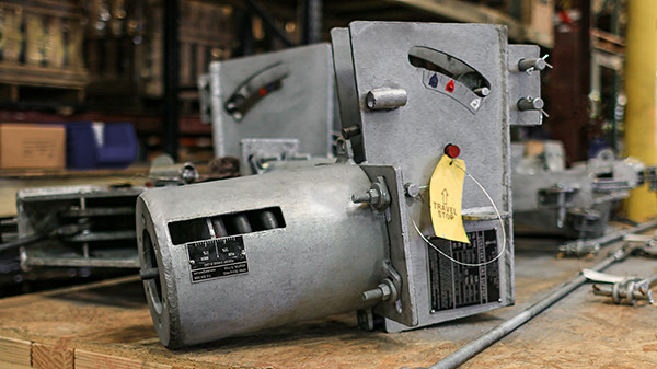
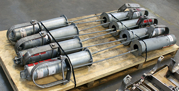
Piping Technology & Products designed these B-Type variable spring supports with clevis hangers for an ethylene cracker plant in Texas. Interestingly enough, we recently supplied over 50,000 supports to one of the largest ethane cracker polymer plants in the US, which was completed last year. In addition to variables, we supplied slide bearing plates, hot and cold insulated shoes/supports, snubbers/sway braces/sway struts, pipe hanger hardware, expansion joints metal bellows, rectangular & circular spacers, davit arms, welded pipe shoes, rod hanger assembly, and wear Pads

On this client order, the variable spring supports, threaded rods, and hex nuts were fabricated from A36 carbon steel, and the clevis hangers from 304 stainless steel. The assemblies are 83-1/8″ in length, and the spring size is 6-80-B. They are designed for an operating temperature of 800°F, an operating load of 619 lb, and 0.5″ of movement. Standard load and travel tests were performed prior to shipment.

PT&P REF. ORIGINAL POST 06052018

Team Delta USA to PT&P

test service nolan

Team Delta USA to PT&P

Team Delta USA Cross Reference to Piping Technology Products

Product Name

PT&P Product Page

Pipe Supports

Adjustable Pipe Supports

Adjustable Pipe Supports

Pre-insulated pipe support

Pre-insulated pipe support

Hold Down Clamps

Hold-down Clamps

Constant & Variable Supports

Constant Spring Support

Constant Spring Support

Variable Spring Support

Variable Spring Support

Sway Struts

Sway Struts

Hot & Cold Insulated Supports

High-temperature pipe support (hot shoes)

High-temperature pipe support (hot shoes)

Cryogenic pipe supports (cold shoes)

Cryogenic pipe supports (cold shoes)

Slide Plates

PTFE, 25% Glass Filled Slide Plates

PTFE, 25% Glass Filled Slide Plates

Bronzphite® Slide Plates

Bronzphite® Slide Plates

Marinite® Slide Plates

Marinite® Slide Plates

Graphite Slide Plates

Graphite Slide Plates

U-Bolts

U-Bolts

Delta Machine to PT&P

test service nolan

Delta Machine to PT&P

Delta Machine Figure Number Cross Reference to Piping Technology Figure Number

Product Name

PT&P Product Page

Pipe Supports

Adjustable Pipe Supports

Adjustable Pipe Supports

Pre-insulated pipe support

Pre-insulated pipe support

Hold Down Clamps

Hold-down Clamps

Constant & Variable Supports

Constant Spring Support

Constant Spring Support

Variable Spring Support

Variable Spring Support

Sway Struts

Sway Struts

Hot & Cold Insulated Supports

High-temperature pipe support (hot shoes)

High-temperature pipe support (hot shoes)

Cryogenic pipe supports (cold shoes)

Cryogenic pipe supports (cold shoes)

Slide Plates

PTFE, 25% Glass Filled Slide Plates

PTFE, 25% Glass Filled Slide Plates

Bronzphite® Slide Plates

Bronzphite® Slide Plates

Marinite® Slide Plates

Marinite® Slide Plates

Graphite Slide Plates

Graphite Slide Plates

U-Bolts

U-Bolts

ASC Engineering Support to PT&P

test service nolan

ASC Engineering Support to PT&P

ASC Engineering Support Figure Number Cross Reference to Piping Technology Figure Number
DescriptionAnvil Figure No.PTP Figure No.
Adjustable Elbow Support---Fig. 260: Adjustable Pipe Elbow Support
Channel AssemblyAnvil Fig. 45Fig. 75: Channel Assembly
Concrete Single Lug PlateAnvil Fig. 47Fig. 74: Concrete Single Lug Plate
Concrete Clevis PlateAnvil Fig. 49Fig. 73: Concrete Clevis Plate
Welding LugAnvil Fig. 55Fig. 72 & 72L: Welding Lug
Steel Washer PlateAnvil Fig. 60Fig. 92: Steel Washer Plate
Welded Beam AttachmentAnvil Fig. 66Fig. 20: Welded Beam Attachment
Adjustable Band HangerAnvil Fig. 69Fig. 2: Adjustable Band Hanger
Vertical Constant Spring SupportAnvil Fig. 80-VFig. PTP 100
Horizontal Constant Spring SupportAnvil Fig. 81-HFig. PTP 200
Short Variable SpringAnvil Fig. 82Fig. PTP-1
Anvil Fig. C-82
Double Variable SpringAnvil Fig. 98Fig. PTP-4
Anvil Fig. C-98
Triple Variable SpringAnvil Triple SpringFig. PTP-6
Quadruple Variable SpringAnvil Quadruple SpringFig. PTP-8
Long Tangent U-BoltAnvil Fig. 137Fig. 100: Long Tangent U-Bolt
Beam ClampAnvil Fig. 133Fig. 130
Anvil Fig. 134
Hanger Rod, Thread Both Ends R.H.Anvil Fig. 140Fig. 128 & 129:Hanger Rod
All Threaded RodAnvil Fig.146Fig. 122: All Threaded Rod
Pipe Covering Saddle for 1" InsulationAnvil Fig. 160Fig. 184: Pipe Covering Saddle for 1" Insulation
Pipe Covering Saddle for 1- p  " InsulationAnvil Fig. 161Fig. 185: Pipe Covering Saddle for 1 to 1/2" Insulation
Pipe Covering Saddle for 2" InsulationAnvil Fig. 162Fig. 186: Pipe Covering Saddle for 2" Insulation
Pipe Covering Saddle for 2-  p  " InsulationAnvil Fig. 163Fig. 187: Pipe Covering Saddle for 2 1/2" Insulation
Pipe Covering Saddle for 3" InsulationAnvil Fig. 164Fig. 188: Pipe Covering Saddle for 3" Insulation
Pipe Covering Saddle for 4" InsulationAnvil Fig. 165Fig. 189: Pipe Covering Saddle for 4" Insulation
Insulation Protection ShieldAnvil Fig. 167Fig. 183: Pipe Insulation Protection Shield
Anvil Fig. 168
Horizontal TravelersAnvil Fig. 170Fig. 270: Horizontal Travelers
Trapeze Roller HangerAnvil Fig. 171Fig. 200: Trapeze Roller Hanger
Roller ChairAnvil Fig. 175Fig. 210: Pipe Roller Chair
RollersAnvil Fig. 177Fig. 215: Adjustable Pipe Roll Support
Roller HangerAnvil Fig. 181Fig. 195: Roller Hanger
Fabricated Clamp RiserAnvil Fig. 40Fig. 190: Fabricated Riser Clamp
Hydraulic Shock and Sway Suppressor (Snubber)Anvil Fig. 200Fig. 2100: Hydraulic Snubbers
Anvil Fig. 201
Anvil Fig. 3306
Anvil Fig. 3307
Sway StrutAnvil Fig. 210Fig. 2110: Sway Strut with 4" of Adjustment
Anvil Fig. 211
Sway Strut---Field WeldedAnvil Fig. 222Fig. 2120: Mini-Sway Strut
Light Two-Bolt Pipe ClampAnvil Fig. 212Fig. 50: Light Two Bolt Pipe Clamp
Heavy Two-Bolt Pipe ClampAnvil Fig. 216Fig. 60: Heavy Two Bolt Clamp
Malleable Beam ClampAnvil Fig. 218Fig. 135: Malleable Beam Clamp
Anvil Fig. 228
Anvil Fig. 292
Yoke U-Bolt, StandardAnvil Fig. 224Fig. 42: Yoke U-Bolt
TurnbuckleAnvil Fig. 230Fig. 30: Turnbuckle
Anvil Fig. 233
Yoke U-Bolt, Heavy DutyAnvil Fig. 246Fig. 43: Heavy Duty Yoke U-Bolt
Light Duty SpringsAnvil Fig. 247Fig. 400-Light Duty Spring Hanger
Eye Rod, Not WeldedAnvil Fig. 248Fig. 120: Eye Rod (Not Welded)
Linked Eye RodAnvil Fig. 248XFig. 126 & 127: Linked Eye Rod
Hanger Rod, Thread One End R.H., One End L.H.Anvil Fig. 253Fig. 128 & 129:Hanger Rod
Cylinder Pipe Guide, Spider GuideAnvil Fig. 255Fig. 6: Cylinder Pipe Guide (Spider Guide)
Anvil Fig. 256
Pipe Saddle Support with U-BoltAnvil Fig. 259Fig. 48: Pipe Saddle Support With U-Bolt
Adjustable Clevis HangerAnvil Fig. 260Fig. 83 Adjustable Clevis Hanger
Anvil Fig. 65
Riser ClampAnvil Fig. 261Fig. 90: Riser Clamp
Adjustable Pipe Saddle SupportAnvil Fig. 264Fig. 46: Adjustable Pipe Saddles
Anvil Fig. 265
Anvil Fig. 192
Standard Variable SpringAnvil Fig. 268Fig. PTP-2
Anvil Fig. B-268
Anvil Fig. C-268
Roller StandAnvil Fig. 271Fig. 230: Roller Stand
Adjustable Roller StandAnvil Fig. 274Fig. 240: Adjustable Pipe Roller Stand
Welded Eye RodAnvil Fig. 278Fig. 110: Eye Rod (Welded)
Welded Linked Eye RodAnvil Fig. 278XFig. 126 & 127: Linked Eye Rod
Weldless Eye NutAnvil Fig. 290Fig. 40: Weldless Eye Nut
Heavy Duty Beam ClampAnvil Fig. 292Fig. 140: Heavy Duty Beam Clamp
Double Bolt Pipe Clamp---CSAnvil Fig. 295Fig. 70: Light Three Bolt Pipe Clamp
Double Bolt Pipe Clamp---AlloyAnvil Fig. 295AFig. 70A: Alloy Three Bolt Pipe Clamp
Heavy Duty Double Bolt Pipe Clamp---CSAnvil Fig. 295HFig. 80: Heavy Three Bolt Clamp
Vibration Control and Sway BraceAnvil Fig. 296Fig. 550 - Sway Braces
Anvil Fig. 297
Anvil Fig. 298
Forged Steel ClevisAnvil Fig. 299Fig. 95: Steel Clevis
Clevis Hanger for Insulated LinesAnvil Fig. 300Fig. 89: Clevis Hanger for Insulated Lines
Vibration Control and Sway BraceAnvil Fig. 301Fig. 555 - Sway Braces
Anvil Fig. 302
Anvil Fig. 303

ASC-ES to PT&P

test service nolan

ASC-ES to PT&P

ASC-ES Figure Number Cross Reference to Piping Technology Figure Number
DescriptionAnvil Figure No.PTP Figure No.
Adjustable Elbow Support---Fig. 260: Adjustable Pipe Elbow Support
Channel AssemblyAnvil Fig. 45Fig. 75: Channel Assembly
Concrete Single Lug PlateAnvil Fig. 47Fig. 74: Concrete Single Lug Plate
Concrete Clevis PlateAnvil Fig. 49Fig. 73: Concrete Clevis Plate
Welding LugAnvil Fig. 55Fig. 72 & 72L: Welding Lug
Steel Washer PlateAnvil Fig. 60Fig. 92: Steel Washer Plate
Welded Beam AttachmentAnvil Fig. 66Fig. 20: Welded Beam Attachment
Adjustable Band HangerAnvil Fig. 69Fig. 2: Adjustable Band Hanger
Vertical Constant Spring SupportAnvil Fig. 80-VFig. PTP 100
Horizontal Constant Spring SupportAnvil Fig. 81-HFig. PTP 200
Short Variable SpringAnvil Fig. 82Fig. PTP-1
Anvil Fig. C-82
Double Variable SpringAnvil Fig. 98Fig. PTP-4
Anvil Fig. C-98
Triple Variable SpringAnvil Triple SpringFig. PTP-6
Quadruple Variable SpringAnvil Quadruple SpringFig. PTP-8
Long Tangent U-BoltAnvil Fig. 137Fig. 100: Long Tangent U-Bolt
Beam ClampAnvil Fig. 133Fig. 130
Anvil Fig. 134
Hanger Rod, Thread Both Ends R.H.Anvil Fig. 140Fig. 128 & 129:Hanger Rod
All Threaded RodAnvil Fig.146Fig. 122: All Threaded Rod
Pipe Covering Saddle for 1" InsulationAnvil Fig. 160Fig. 184: Pipe Covering Saddle for 1" Insulation
Pipe Covering Saddle for 1- p  " InsulationAnvil Fig. 161Fig. 185: Pipe Covering Saddle for 1 to 1/2" Insulation
Pipe Covering Saddle for 2" InsulationAnvil Fig. 162Fig. 186: Pipe Covering Saddle for 2" Insulation
Pipe Covering Saddle for 2-  p  " InsulationAnvil Fig. 163Fig. 187: Pipe Covering Saddle for 2 1/2" Insulation
Pipe Covering Saddle for 3" InsulationAnvil Fig. 164Fig. 188: Pipe Covering Saddle for 3" Insulation
Pipe Covering Saddle for 4" InsulationAnvil Fig. 165Fig. 189: Pipe Covering Saddle for 4" Insulation
Insulation Protection ShieldAnvil Fig. 167Fig. 183: Pipe Insulation Protection Shield
Anvil Fig. 168
Horizontal TravelersAnvil Fig. 170Fig. 270: Horizontal Travelers
Trapeze Roller HangerAnvil Fig. 171Fig. 200: Trapeze Roller Hanger
Roller ChairAnvil Fig. 175Fig. 210: Pipe Roller Chair
RollersAnvil Fig. 177Fig. 215: Adjustable Pipe Roll Support
Roller HangerAnvil Fig. 181Fig. 195: Roller Hanger
Fabricated Clamp RiserAnvil Fig. 40Fig. 190: Fabricated Riser Clamp
Hydraulic Shock and Sway Suppressor (Snubber)Anvil Fig. 200Fig. 2100: Hydraulic Snubbers
Anvil Fig. 201
Anvil Fig. 3306
Anvil Fig. 3307
Sway StrutAnvil Fig. 210Fig. 2110: Sway Strut with 4" of Adjustment
Anvil Fig. 211
Sway Strut---Field WeldedAnvil Fig. 222Fig. 2120: Mini-Sway Strut
Light Two-Bolt Pipe ClampAnvil Fig. 212Fig. 50: Light Two Bolt Pipe Clamp
Heavy Two-Bolt Pipe ClampAnvil Fig. 216Fig. 60: Heavy Two Bolt Clamp
Malleable Beam ClampAnvil Fig. 218Fig. 135: Malleable Beam Clamp
Anvil Fig. 228
Anvil Fig. 292
Yoke U-Bolt, StandardAnvil Fig. 224Fig. 42: Yoke U-Bolt
TurnbuckleAnvil Fig. 230Fig. 30: Turnbuckle
Anvil Fig. 233
Yoke U-Bolt, Heavy DutyAnvil Fig. 246Fig. 43: Heavy Duty Yoke U-Bolt
Light Duty SpringsAnvil Fig. 247Fig. 400-Light Duty Spring Hanger
Eye Rod, Not WeldedAnvil Fig. 248Fig. 120: Eye Rod (Not Welded)
Linked Eye RodAnvil Fig. 248XFig. 126 & 127: Linked Eye Rod
Hanger Rod, Thread One End R.H., One End L.H.Anvil Fig. 253Fig. 128 & 129:Hanger Rod
Cylinder Pipe Guide, Spider GuideAnvil Fig. 255Fig. 6: Cylinder Pipe Guide (Spider Guide)
Anvil Fig. 256
Pipe Saddle Support with U-BoltAnvil Fig. 259Fig. 48: Pipe Saddle Support With U-Bolt
Adjustable Clevis HangerAnvil Fig. 260Fig. 83 Adjustable Clevis Hanger
Anvil Fig. 65
Riser ClampAnvil Fig. 261Fig. 90: Riser Clamp
Adjustable Pipe Saddle SupportAnvil Fig. 264Fig. 46: Adjustable Pipe Saddles
Anvil Fig. 265
Anvil Fig. 192
Standard Variable SpringAnvil Fig. 268Fig. PTP-2
Anvil Fig. B-268
Anvil Fig. C-268
Roller StandAnvil Fig. 271Fig. 230: Roller Stand
Adjustable Roller StandAnvil Fig. 274Fig. 240: Adjustable Pipe Roller Stand
Welded Eye RodAnvil Fig. 278Fig. 110: Eye Rod (Welded)
Welded Linked Eye RodAnvil Fig. 278XFig. 126 & 127: Linked Eye Rod
Weldless Eye NutAnvil Fig. 290Fig. 40: Weldless Eye Nut
Heavy Duty Beam ClampAnvil Fig. 292Fig. 140: Heavy Duty Beam Clamp
Double Bolt Pipe Clamp---CSAnvil Fig. 295Fig. 70: Light Three Bolt Pipe Clamp
Double Bolt Pipe Clamp---AlloyAnvil Fig. 295AFig. 70A: Alloy Three Bolt Pipe Clamp
Heavy Duty Double Bolt Pipe Clamp---CSAnvil Fig. 295HFig. 80: Heavy Three Bolt Clamp
Vibration Control and Sway BraceAnvil Fig. 296Fig. 550 - Sway Braces
Anvil Fig. 297
Anvil Fig. 298
Forged Steel ClevisAnvil Fig. 299Fig. 95: Steel Clevis
Clevis Hanger for Insulated LinesAnvil Fig. 300Fig. 89: Clevis Hanger for Insulated Lines
Vibration Control and Sway BraceAnvil Fig. 301Fig. 555 - Sway Braces
Anvil Fig. 302
Anvil Fig. 303

B Type & C Type Constants for an Oil Refinery in Louisiana

test service nolan

B Type & C Type Constants for an Oil Refinery in Louisiana

Type: B-Type & C-Type Constant Spring Supports
Size: 12″ x 18″ x 20″ to 12″ x 12″ x 32″
Material: A36 Carbon Steel | Hot-dipped Galvanized
Design: Operating Load Range: 475 lb. to 1,250 lb.
Movement of 2-1/4″ to 5″
Testing: Q.C. Inspection | Load and Travel Tests

PT&P fabricated multiple B-Type and C-Type constant spring supports for an oil refinery in Louisiana. The constants are fabricated from A36 carbon steel and hot-dipped galvanized. The dimensions range from 12” x 18” x 20” to 12” x 12” x 32”. The operating load range is 475 lb. to 1,250 lb. with movement of 2-1/4” to 5”. Standard load testing was completed to ensure quality and performance.

PT&P REF. ORIGINAL POST 05042020

Top