What Every Plant Manager Needs to Know About Pipe Stress Analysis

test service nolan

Pipe stress analysis blog project manager graphic (1)

If you manage a process plant, power facility, or oil and gas operation, you know that piping systems are at the center of your entire operation. But how often do you think about the hidden forces: the intense pressures, temperature shifts, and vibrations that are constantly pushing your pipes to their breaking point?

Ignoring these forces isn’t just a risk; it’s a guaranteed path to costly downtime, failures, and safety hazards. This is where pipe stress analysis comes in: it’s the essential engineering practice that ensures your piping system not only works but lasts.

What Exactly is Pipe Stress Analysis?

Caesar2

CAESAR II PSA

Pipe stress analysis is a systematic, mathematical study used to evaluate the stresses and displacements in a piping system. Think of it as a comprehensive health check-up for your pipes.

An engineer uses specialized software to build a virtual model of your entire system. They then subject this model to all the real-world conditions it will face:

  1. Pressure: The internal force from the fluid or gas being transported.
  2. Temperature: The thermal expansion and contraction that occur as the fluid’s temperature changes (often the single biggest source of stress).
  3. Weight: The dead weight of the pipe, fluid, and insulation.
  4. External Loads: Forces from wind, seismic activity (earthquakes), or external equipment (like pumps or valves).

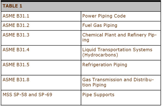
The goal is to verify that the stress imposed on the pipe wall, fittings, and supports remains within the limits defined by industry codes, such as ASME B31.3 for process piping.

Why Is This Analysis Critical for Your Operation?

Skipping or shortchanging pipe stress analysis is a classic example of being penny-wise and pound-foolish. The costs of a failure far outweigh the cost of analysis.

1. Prevent Catastrophic Failure and Leaks

The most immediate benefit is safety. Excessive stress can lead to fatigue cracking, flange leaks, or even a sudden rupture. Analysis ensures that your system can handle every operational scenario without a catastrophic failure that endangers personnel and the environment.

2. Protect Expensive Equipment

Piping doesn’t exist in a vacuum; it connects to critical, often multi-million-dollar equipment such as pumps, turbines, and heat exchangers. If a pipe expands excessively and pulls on a connected nozzle, it can cause severe damage or destruction to that equipment, resulting in substantial replacement costs and prolonged downtime.

3. Ensure Reliability and Uptime

A properly analyzed and supported system experiences less vibration, less wear on supports, and fewer flange leaks. This directly translates into higher operational reliability, minimizing unexpected shutdowns —the biggest drain on a plant’s profitability.

4. Improve Support Selection

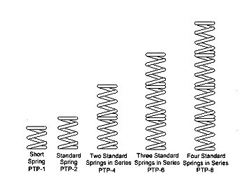
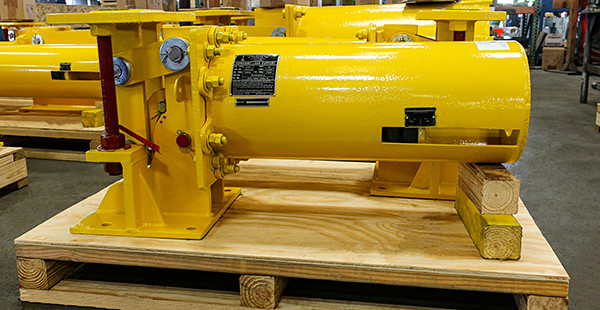
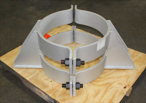
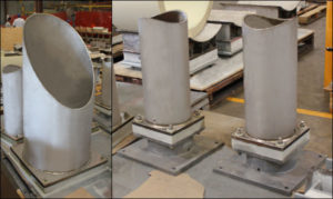
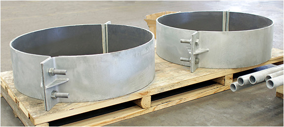
This is where analysis meets reality. Once the stress engineer knows where the forces are greatest, they can correctly design and specify the right supporting elements. Are standard clamps enough, or do you need specialized solutions such as pipe shoes, slides, or anchors to manage movement and transfer loads safely to the structure?

Pipe Stress Analysis Software
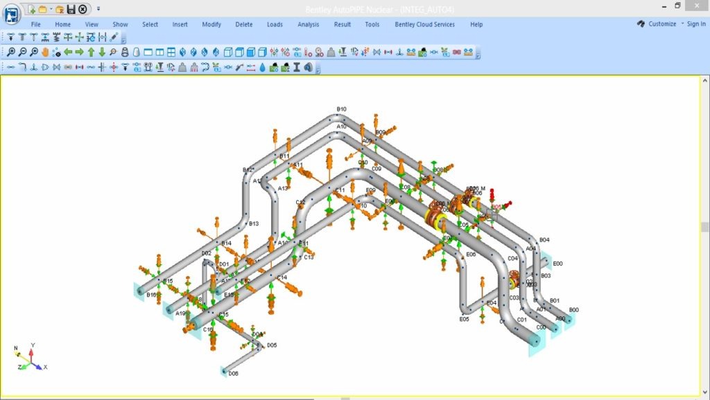
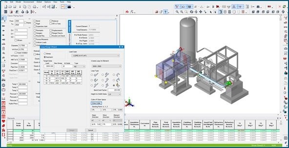
Autopipe psa

AutoPIPE PSA

Performing a thorough pipe stress analysis is a task too complex and iterative to be done manually. Specialized pipe stress analysis (PSA) software is essential for creating detailed virtual models, applying various load cases, and performing the millions of calculations required to comply with industry codes.

These sophisticated programs allow engineers to:

  • Rapidly model complex pipe routing, components (valves, fittings), and support structures.
  • Accurately simulate real-world conditions like thermal expansion, seismic events, wind load, and transient conditions (e.g., water hammer).
  • Automatically check results against stringent design codes (e.g., ASME B31.3, B31.1) to confirm compliance.

A few key players dominate the market, each offering powerful tools with slightly different specialties and features. The most recognized and widely used software packages globally include:

  • CAESAR II (Hexagon): Arguably the industry standard, known for its extensive code compliance checking and user-friendly interface.
  • AutoPIPE (Bentley Systems): Highly capable, often praised for its integration with CAD and structural analysis programs.
  • CAEPIPE (SST Systems): A well-established tool favored for its speed and intuitive graphical user interface (GUI).

Selecting the right software is crucial, as its accuracy and features directly impact the reliability of your final design. The results of this virtual analysis guide real-world decisions about where and how to place the critical pipe supports.

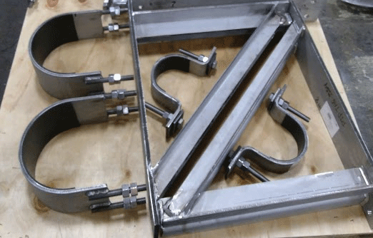
The Support Solution is Key

Stress analysis identifies the problem, but pipe supports are the engineered solution. If a study shows excessive movement or load on a critical elbow, the correct support, chosen for its material, design, and load capacity, is essential to resolve the issue.

At Pipe Shields, we specialize in high-quality, engineered supports that implement the findings of your stress analysis. We turn theoretical safety into physical reliability. By using the right shields, slides, and clamps, you ensure that the structure in the field safely manages the stresses calculated in the model.

Your Piping System Can’t Talk, But Our Piping Technology Team Can Read Its Stresses

Pipe stress analysis is the first step to guaranteed piping integrity. It’s not just a compliance checkbox; it’s a fundamental investment in your plant’s future.

Piping Technology & Products (PT&P) is the essential physical assurance against the high costs of piping failure.

After your pipe stress analysis identifies critical stress points, we provide the precisely engineered supports (pipe shoes, guides, slides) that safely absorb and dissipate those forces, protecting your multi-million-dollar equipment and protecting your investment in piping infrastructure. Get started with a PT&P pipe stress analysis now.

Don’t wait for a leak or a failure to realize your piping system is under-designed. Speak with one of our experts to receive a customized quote to improve safety and extend the lifespan of your piping system.  

Variable Spring Sizing

test service nolan

Download PDF

Piping systems are used to transport gases, liquids and suspended solids between units of a plant. The temperatures of the contents and the pipe when the plant is in operation are often quite different from the ambient temperature of the surroundings. The heat transferred during changes in temperature causes metal pipes to expand and contract. Piping designers must provide for movement due to temperature changes and forces caused by pumps, gravity, and other elements of the piping system.

Proven engineering practices are included in various codes for piping services developed by professional societies such as the American Society of Mechanical Engineers. Most companies use these codes to develop specific standards for their products. The Manufacturers’ Standardization Society has developed standards for pipe supports. Designs that satisfy codes are important to satisfy laws and to obtain financing and insurance for projects. Table 1 provides a list of some important standards.

Variable Spring Assembly Line

PT&P’s Variable Spring Assembly Line

Variable Spring Supports Ready for Shipment

Variable Spring Supports Ready for Shipment


Variable springs are one of the most important devices available to help support pipes. They are used to balance the concentrated gravitational load of vertical sections of pipe while allowing for thermal movement. Control of the direction and amount of movement of various sections of pipe is a major function of piping design. Computer models are used during design to predict the forces and movement at the point where a spring support is attached to the pipe. This is the information required to select the least expensive variable spring to use.

Variable springs are relatively inexpensive and very reliable. When replacement is necessary, the engineer needs to determine if the original size is still appropriate or if the system has changed and different forces and movement must be considered.

Table 1

Pipe support manufacturers product catalogs which describe the items they routinely supply. The engineered spring support section of our catalog contains detailed information on variable springs. The load and travel tables contain the information required to size variable springs. An abbreviated version of this table is given in Figure 6.


Physics of Spring Coils

Variable spring supports are attached to piping systems so the coil is in a vertical position as shown in Figure 1. Forces which compress the coil act in the same direction as the force of gravity. Movement due to temperature changes may be either up or down. Movement is a vector which has both direction (up or down) and magnitude. Travel is a scaler which describes the length of movement or compression of the spring coil.

A spring can only be compressed so much before the individual coils come together and it “goes solid”. The usual method used to provide for larger travel is to provide a longer coil or stack standard coils together as shown in Figure 2.

Force of GravitySpring Sizing Scale

Newton’s Third Law of Motion states that every force is accompanied by an equal and opposite force. A spring coil resists the force which compresses it. The more the coil is compressed, the greater resistance it has to further compression. This is why pipe supports which apply forces directly to the spring coil are called variables.

The magnitude of the force required to compress a spring coil depends on the size of the wire used to form the coil and on the diameter of the coil. A “stronger” coil can be produced by using a larger wire or by winding the wire “tighter”. The two industry standards are the PTP-1 (short spring) and the PTP-2 standard spring. Twenty-three different wire sizes from .23 inches to 2.5 inches are used to increase the size of the force required to compress the coil. At PT&P, we use 00, 10,…,200, 210, 220 to designate the wire size (resistance to force) of the coil as shown in the top of Figure 6.

Figure 3 shows a graph of pounds-force required to compress a PTP-2, size 90 coil as a function of the amount of compression. The graph is a straight line through the origin with a slope of 200 pounds-force per inch of compression. The slope of this line is the spring rate of this variable support. We compress the coil three inches during assembly (using 600 pound-force). The variable produced can be further compressed an additional 3.5 inches (range of deflection) by applying 1300 pounds-force. Each additional 200 pounds-force will compress the coil one inch.


Figure 3

Manufacturers recommend that only 80% of the range of deflection (called the operating range) be used for variables. The PT&P load and travel table uses red lines to enclose the loads in the operating range. Figure 3 marks both the minimum and maximum loads (700 and 1200 pounds-foce) for the operating range with red lines. The load at the center of the operating range (950 pounds-force) is marked with a blue line. The total compression of the coil at 700 pounds-force is 3.5 inches and the compression at 1200 pounds-force is 6.0 inches so the operating range is 2.5 inches.

Figure 6. shows how to obtain these values from the load and travel table of our catalog.
Figure 4

Selecting the Proper Size for a Variable

The coil size (force required for compression) should be chosen to balance the expected force on the support when the system is operating. To do this, choose the size (00 to 220) which has its center compressive force (blue line) in Figure 6 as close as possible to the Operating Load (“hot load”). Choose the shortest (least expensive) coil and operating range which will satisfy the expected movement the support will experience during the temperature changes expected going from cold load (non-operating force applied) to operating load.

Figure 5 illustrates the relation between the three quantities, operating load, cold load and movement. The direction of movement is defined by the change of load (force on the support) when the system changes from cold to operating. If the operating load is greater, the increase in the force will further compress the coil so the direction of the movement is down. If the operating load is smaller, the decrease in the force on the support will allow the coil to expand so the movement is up.


Figure 5

Figure 6

Variability Constraint

The change in the force on the support when changing from cold to operating is equal to the spring rate multiplied by the Travel (magnitude of the movement). Good practice as specified in MSS code requires that this change experienced by the support should be no more than 25% of the operating load, thus the inequality in Equation (a) must always be satisfied. Note that the spring rate is a function of both the coil size (Z) and the coil length (X). Coil size Z is chosen to match the operating load, so X is chosen as small as possible to satisfy Equation (a). The possible values of X are 1,2,4,6, and 8 which correspond to PTP-X and define the operating range of the support.


(a) Spring Rate (Z,X) * Travel < 0.25 * Operating Load

Variable Spring Coils and Variable Spring

If you are interested in a computer program that will size variable spring supports shown in the PT&P catalog, you can download here.

U-Type Constants Designed with Slide Plates for a Polypropylene Plant in Texas

test service nolan

147164a1

Constants use a spring coil (or series of coils) to accommodate pipe movement from the initial (installed) condition to the final (operating) condition of the piping system. For all constant spring supports, there is no difference in load, and the supported load will remain uniform throughout the deflection cycle.

PT&P designed and fabricated a U-Type constant spring support , with PTFE and a 25% glass-filled side plate for a Polypropylene Plant in Texas. The constant is fabricated from carbon steel and hot-dipped galvanized for extra protection against corrosion. The vertical movement is 1.5″ total upward travel and is capable of supporting a load of 10,350 lbs. throughout its range of movement. The constant underwent standard load testing prior to shipment.

Along with chemical plants, constant spring supports are utilized in refineries, power plants, and heat recovery steam generators (HRSG). The design of the constant spring support replaced a system of pipe support called a “counterweight” design still used in some facilities today. The counter-weight system utilized pipe clamps or lugs (attached or welded to the pipe), cables, pulleys, and a set of weights. Just like the old-fashioned brass weighing scales, weights were added to one end of the pulley system until an equilibrium was reached. The counterweight design needed a large amount of space with which to operate. Constant spring hangers replaced this system because they require much less space in order to function (similar to some designs we stand on to weigh ourselves). No matter the application, our team of experienced engineers and designers can help to resolve your pipe support needs. Please contact us via our 24×7 emergency service or send an email to info@pipingtech.com.

PT&P REF. ORIGINAL POST 08232016

Cold Shoes and Hot Shoes Designed for an Ammonia Project

test service nolan

Insulated Pipe Supports Designed for Cryogenic and High Temperature Pipe Systems for an Ammonia Project

Insulated pipe supports are designed to prevent direct heat transfer between pipes and their supports. Thus, they prevent heat loss due to conduction at each support. Whether a cold or hot temperature pipeline, the transfer from cold to hot or hot to cold is prevented.  They serve the following purposes: Carry the load and allow necessary movement (when used with slide plates) at each point of support, provide insulation in the support area where the regular pipe insulation is not sufficient to support the load and minimize installation costs by reducing the time required to install the support. The supports are not welded to the pipe, and each unit is shipped completely assembled (except for the riser supports and anchor supports, both of which require some welding).  In HVAC and plumbing applications, insulated supports also help prevent condensation and corrosion under insulation (CUI) by maintaining the vapor barrier at the support point. Their use contributes to better energy performance, reduced maintenance, and compliance with MEP design standards focused on energy efficiency and moisture control in building systems.

For this project, we custom-designed 98 insulated pipe supports for an ammonia project at a chemical plant in Louisiana. The supports were designed for both cryogenic and high-temperature pipe systems, with an 8″ to 22″ baseplate width and a 10″ to 28″ saddle length. They were designed for pipe diameters of 6″-24″ and are composed of polyurethane foam for cryogenic and high-density calcium silicate insulation for high temperatures. Standard Q.C. and dimensional tests were performed prior to shipment.  

This project was a combination of upgrading a current anhydrous ammonia plant and adding new capacity to the facility.  We worked with the EPC, on-site contractors, and operators to ensure specifications and delivery deadlines were met over a three-year period during project construction.  In addition to the insulated supports discussed here, we designed, manufactured, and shipped bellmouth reducers, metallic expansion joints, pipe shoe guides and anchors, pipe hanger hardware, slide plates, snubbers, sway braces, struts, and variable spring supports.

Beyond ammonia and chemical processing facilities, insulated pipe supports are widely used across other industries where thermal control and system integrity are essential. These include petrochemical plants, LNG and cryogenic gas facilities, power generation plants, and district energy systems for heating and cooling networks. They are also integral to MEP infrastructure in data centers, pharmaceutical manufacturing, and food processing plants, where preventing condensation and maintaining precise temperature control are critical. In each of these applications, insulated supports help maintain energy efficiency, protect against corrosion under insulation, and ensure long-term reliability of piping systems operating under extreme temperature conditions.

PT&P REF. ORIGINAL POST 06232015

F-Type Constant Spring Supports Designed and Manufactured for Gas Plant

test service nolan

F-Type Constant Spring Supports Designed and Manufactured for Gas Plant

Type: F-Type Constant Spring Supports
Size: 36″- 87″ Length | 24″ Height
Material: A36 Carbon Steel | HDG | SS Slide Plates
Design: 13,500 lb. Load | 250°F | 17.5″ Travel
Testing: Q.C. Inspection | Load and Travel Tests

We custom-designed multiple horizontal F-Type constant spring supports for a series of offshore gas platforms located in the Persian Gulf, near the coast of Saudi Arabia. These constants feature stainless steel slide plates and are engineered for a total travel of 17.5 inches. Fabricated from carbon steel, they are hot-dipped galvanized and coated with a specialized three-layer paint system to withstand the harsh, highly corrosive environment. Per the client’s specification,  the topcoat is painted “Safety Yellow” for easy identification.

To further enhance corrosion resistance, the bolting assemblies used in constructing these units were coated with a fluoropolymer, which also helps to reduce friction and wear. Each assembly measures 24 inches in height and ranges from 36 to 87 inches in length. They are designed to operate at temperatures up to 250°F and handle loads of up to 13,500 pounds. Load testing and dye penetrant inspections were performed in-house to ensure quality and reliability before shipment.  Our manufacturing is based on a long test and reliability work methodology, with our roots in engineering and design when we started as a pipe stress company.  In addition to manufacturing the products our customers design for their specific applications, we also conduct testing to meet both our quality standards and their requirements.  

F-type constants manage loads, thermal compensation, vibration dampening, and vertical and lateral movements in piping systems.  We have supplied constants for a myriad of end applications worldwide.  The industries we have worked with that need this kind of product in their piping systems include: 

  • Energy and Oil & Gas
  • Chemical and Petrochemicals
  • Renewable Energy and Sustainability 
  • Industrials and Manufacturing
  • Automotive
  • Semiconductor
  • Pulp and Paper
  • Utilities and Power
  • Construction and Building Materials 

We have optimized our manufacturing process to offer an unparalleled range of customization options with minimal impact on delivery timelines. In addition to our standard (hot-dipped galvanized carbon steel with neoprene-coated spring coils) constant spring supports, we can customize any material, finish, dimension, load, load adjustment, travel, and travel stops, as well as provide sensors for remote monitoring. 

Historically, obtaining a custom-designed constant spring support posed a significant challenge in terms of both design and manufacturing, with lead times extending to a minimum of 6-8 weeks.

Through a dedicated focus on manufacturing optimization and employing a design-centric engineering approach, we have reduced the required manufacturing time by more than half. The process of acquiring custom constant spring supports is now significantly streamlined. In fact, we are capable of fulfilling emergency orders in less than 24 hours, taking into account the client’s location and urgent requirements.

We can also provide the services of our well-trained field service teams for installation guidance, should it be needed.  

At our Houston-based facility, we design and manufacture constant spring supports with unmatched speed and precision. Operating 24/7, we are equipped to handle both small emergency orders and large-scale production needs. Our wide range of industry expertise demonstrates our unique ability to provide solutions across the globe in every sector we serve.


Unlocking Pipeline Efficiency: The Ultimate Guide to Pig Launchers

test service nolan

Us bellows pig launcher

Your pipeline is the circulatory system of your operation, and just like a human body, it requires routine maintenance to function at its peak. 

In chemical and petrochemical industries, pigging systems are used to separate different products within a pipeline to prevent contamination, as well as for cleaning and inspection. In water and wastewater treatment, they help remove sediment, biofilms, and scale from municipal mains to improve water quality and flow efficiency. In the food and beverage sector, pigging is employed to reclaim valuable products and prevent cross-contamination when transporting different batches of liquids such as chocolate, dairy, or juices. Similarly, in pharmaceuticals and cosmetics, pigging is applied in sanitary processes to clean and inspect pipelines, ensuring product purity and compliance with strict hygiene standards.

Pigging: the act of using a device called a “pig” to clean, inspect, or maintain a pipeline, is the most effective way to achieve optimal performance from your piping operation. And at the center of any successful pigging program is the pig launcher.

A pig launcher is a specialized piece of equipment that safely introduces a pipeline pig into a pressurized line. It’s a critical component that delivers efficient and safe pigging operations. 

Choosing the right one is important. This guide will help you understand the benefits and options available, enabling you to make an informed choice that will aid in maintaining a debris-free piping operation.

Equipment

The physical infrastructure is essential for any pigging operation. This equipment, including pig launchers and receivers, enables the safe and efficient introduction and removal of pigs from the pipeline.

  • Pig Launcher: An oversized section of pipe where a pig is loaded and then launched into the main pipeline. It’s equipped with a quick-opening closure for easy access and various valves to control pressure and fluid flow.
  • Pig Receiver: Located at the end of a pigging run, this is a similar oversized section of pipe designed to catch the pig and any debris it pushes. It also features a quick-opening closure for retrieving pigs and debris.
  • Kicker and Bypass Lines: The kicker line is a smaller pipe that directs a portion of the product flow into the launcher to propel the pig. Bypass lines are used in receivers to allow continuous product flow while the pigging process is underway.

Why Pig Launchers Are Important for Your Piping Operation

Investing in a quality pig launcher isn’t just about maintenance; it’s about safeguarding your assets and maximizing your return. The benefits extend far beyond a clean pipe:

  • Boosted Productivity and Flow: Debris, wax, and scale buildup inside pipelines can restrict flow, increase friction, and reduce overall throughput. Regular pigging removes these blockages, improving flow rates and boosting operational efficiency.
  • Reduced Operational Costs: By recovering valuable products, minimizing waste, and decreasing the need for extended shutdowns for manual cleaning, pigging systems can lead to significant cost savings.
  • Increased Safety: Modern pig launchers are designed with safety features, such as quick-opening closures and pressure relief devices, to protect personnel and equipment during operations, thereby mitigating risks associated with high-pressure systems.
  • Product Batching and Separation: For companies that transport different products through the same pipeline, pigging allows for the effective separation of batches, preventing cross-contamination and ensuring product purity.

For a deeper dive into how custom solutions can address specific challenges, read our companion piece: Custom-Designed Pig Launcher.

Your Options: Choosing the Right Pig Launcher

Pig launchers are not one-size-fits-all. They are highly customized based on your specific application, pipeline dimensions, and operational needs. Here are the key factors you need to consider:

Sizing and Pressure

The most important considerations are the size of your pipeline and the operating pressure. The launcher’s major barrel must be large enough to hold the pig, while the minor barrel must match the diameter of the pipeline. Our capacity for design pressure range is up to  4000 PSIG (pounds per square inch gauge) for pig launchers and receivers:

Material Selection

The material of the launcher is critical for lifespan, application, and media integrity . Most are fabricated from carbon steel, but for corrosive or sanitary/food grade applications (e.g., food and beverage/pharma), materials like stainless steel are often required to prevent contamination and withstand harsh environments.

Level of Automation

Pig launchers come with various levels of automation. From simple, manually operated systems with flag indicators to fully automated, remotely controlled units, the choice depends on your budget and the frequency of pigging operations. Automated systems reduce operator involvement, increase safety, and enable more frequent and aggressive pigging programs.

Things We Need to Know, Before We Quote a Pig Launcher or Receiver 

  • What will the launcher be used for, liquid or gas? This will determine the design code.
  • What will be the pressure and temperature of the fluids in the operating system?
  • Will you need supports (legs) to be included?
  • What type of finish will you select? The standard finish is our shop primer.
  • Do you have any special requirements? Anything added to a launcher or receiver can increase both complexity and cost.
  • What is the location of closure, where the pig will be loaded? As pressure requirements increase, closure options become more restrictive.

Specialized Features

To optimize your system, consider these options:

  • Quick-Opening Closures: These are essential for safe and rapid access to the launcher barrel, allowing for the insertion or retrieval of the pig.
  • Instrumentation Ports: These allow for pressure monitoring, while vents and drains are crucial for depressurization and cleaning.
  • Bypass Lines: A bypass allows product flow to continue while the launcher is offline for maintenance.

Multiple-Pig Systems: For complex operations, launchers can be designed to hold and launch multiple pigs in sequence, which is ideal for multi-stage cleaning or intelligent inspection.

At Sweco Fab, a Piping Technology & Products company, we offer the following capabilities for pig launchers and receivers:

Fabrication Design Codes Materials of Construction Design Pressure Range Pig Trap Size Ranges Maximum Overall Skid Offered Shop Certifications
ASME B31.4, B31.8, B31.4 & Sec. VIII Div.1 CS, LTCS, SS 304, SS316 & API Pipes Up to 4000 PSIG Line 2″ NPS to 48″ NPS Lines 8′ x 40′ x 10′ (Up to 40,000 Lbs weight capacity) ASME U & R Stamp certified, ISO 9001

Don’t Leave Your Pipeline to Chance: Partner with Piping Technology & Products (PT&P)

Every pipeline is a significant investment, and its performance directly impacts your bottom line. By selecting the right pig launcher and receiver system, you can ensure continuous operation and protect your infrastructure. The decision to pig your pipeline is the first step toward a smarter, more profitable operation. The next step is choosing a partner like PT&P who can provide the right solution, tailored to your exact specifications.

Ready to boost performance and safety in your pipeline operations? Contact our experts and request a quote today to design a custom pig launcher.

September 2025 News: PT&P is Awarded the ISO Certificate

test service nolan

PT&P is Now ISO 9001:2015 Certified (09-05-2015)
Piping Technology & Products, Inc. is awarded the ISO 9001:2015 certificate by DNV Certification, a division of Det Norske Veritas (DNV), for the Manufacture of Hot and Cold Pipe Supports. This certificate proves that PT&P’s Quality Management System has been certified against the best practice standard and is compliant.

ISO 9001:2015

View ISO 9001:2015 Certificate

The latest version of standards, ISO 9001:2015 is created by the International Organization for Standardization (ISO), who set international requirements for Quality Management Systems. By conforming to the Quality Management System, Piping Technology & Products, Inc. demonstrates predictability of internal operations and the ability to meet customer requirements. While becoming certified, a company can identify the areas that are most critical to operations through management system audits. Once problem areas are identified, measured, managed and improved, customer satisfaction will rise, staff responsibility and motivation will also experience growth.

Built for Real-World Vertical Support: Custom Riser Clamp Assemblies That Hold the Line

test service nolan

Pipe Clamp Assemblies Custom Designed for a Partial Oxidation Unit in a Synthetic Gas Plant

When vertical piping in a high-pressure system starts to shift, everything downstream is at risk. Hanger misalignment, accessory failure, and field delays would be the least of your worries when vertical pipe systems experience axial displacement. 

That’s where Piping Technology & Products’ custom riser clamp assemblies deliver assurance engineers can count on. With the proper design specifications, PTP can manufacture precision riser clamps that ensure secure and reliable product delivery.

Purpose-Built for Vertical Load Control

Riser clamp assemblies are specifically engineered for vertical pipe systems where axial movement must be restricted. It is not a one-size-fits-all product. Each assembly is fabricated to fit exact pipe diameter, temperature, and load specifications, most commonly for critical process lines in synthetic gas, petrochemical, or tall vertical rack applications.

At its core, the assembly relies on a heavy-duty steel clamp secured around the pipe, working in tandem with thrust plates to manage axial loads. 

For high-heat applications, manufacturers utilize A387 alloy steel (rated for service temperatures of 750°F to 1,000°F) and a high-temperature coating that won’t degrade or flake under scorching conditions.

Once installed, the clamp limits movement in the downward direction, ensuring the pipe doesn’t slip under load or due to temperature expansion. Engineers often pair the clamp with spring hangers or sway struts for a complete load path solution.

Real-World Application: Synthetic Gas Plant Retrofit

At the request of a synthetic gas facility, PTP engineered a custom riser clamp assembly for their high-temperature vertical piping. We used Alloy A387, a heat-resistant steel specifically selected for service temperatures reaching up to 1,000°F, to fabricate this assembly. 

To ensure performance under thermal cycling, we coated the clamp with a high-temperature industrial-grade coating designed to withstand prolonged exposure without degradation. By preventing vertical slippage during system startup, the clamp maintained alignment integrity and eliminated the risk of early rework or other types of damage to the pipeline.

Common Use Cases for Riser Clamp Assemblies

Riser pipe clamp assemblies serve a critical role in applications where vertical piping must be securely supported and restrained. 

Engineers commonly use them on vertical risers in fired heater loops, where high temperatures and axial loads demand reliable restraint. They also support tall structural pipe racks in petrochemical plants, ensuring alignment across multi-level piping systems. 

In high-rise and offshore environments, riser clamps provide secure anchoring for firewater systems subject to seismic or dynamic loading. Additionally, LNG facilities rely on them for vertical steam lines that require thermal movement control and long-term integrity.

Key Benefits for Field Execution

PT&P’s custom riser clamp assemblies provide clear advantages for vertical piping systems. 

They prevent pipe slippage by firmly securing the line in place, ensuring axial stability under load. 

Each assembly is custom-sized to match the exact pipe outer diameter, specified load, and temperature range, eliminating fit-up issues during installation. 

PT&P designs these supports to handle pipe sizes up to 48 inches and fabricates them with high-temperature materials and coatings that perform reliably in scorching environments. 

Engineers apply Finite Element Analysis (FEA) to optimize steel thickness, reduce excess material, and validate structural integrity. 

By managing design, fabrication, and delivery in-house, PT&P minimizes handoffs and reduces the risk of delays or errors throughout the supply chain.

Why Engineers Choose Riser Clamp Assemblies

Engineers value this clamp for its precision and structural integrity. Load ratings are validated through FEA, ensuring that the clamp can stand against almost any surprise event. For jobs with elevated temperatures or non-standard loads, our custom approach removes guesswork from spec compliance.

Why Project Managers Chose Riser Clamp Assemblies

What sets these clamps apart is how they minimize scope creep. 

When clamp assemblies are properly designed from the start, there’s no field modification, no install surprises, and fewer RFIs. The result: less rework, better schedule control, and a clear value add during procurement planning.

Other Items Often Purchased with Riser Pipe Clamp Assemblies

Talk to an Engineer

Need a riser clamp that fits your piping system? Our team is ready to review your load, pipe size, and environment to build the right assembly fast.

Request a Quote or Talk to an Engineer today.

Trunnion Base ELL (Elbow) Pipe Supports for Cryogenic Piping: Proven Thermal Isolation and Custom Fit

test service nolan

Trunnion Base ELL Supports for a Cryogenic Line

What is a Trunnion Pipe Support?

A trunnion pipe support is a structural component used to support a piping system and is connected directly to the process line. It functions as a secondary pipe element, helping hold the main line in position for stability.  ASME standards guide their application and analysis to ensure safety and reliability, particularly in high-energy piping and under various operating conditions. 

In standard applications, trunnions are used to:

  • Support sections of pipe vulnerable to weight or stress
  • Help manage pressure at directional changes like elbows
  • Provides added stability and structural strength by helping reinforce the system at critical load points
  • Prevent displacement under heavy loads or external forces

In cryogenic systems, however, added challenges emerge. Maintaining thermal insulation at support points is critical. Without it, heat transfer through the support could lead to the evaporation of liquids into gases, cause condensation, and/or result in ice buildup. Over time, this can damage the pipe or disrupt flow.

Custom Trunnion Base ELL Pipe Supports for Cryogenic LNG Applications

Trunnions Designed with Insulation for an LNG Facility

At an LNG gasification facility, our customer required pipe supports that could prevent the transfer of heat and provide trunnion-like stability and strength. Piping Technology & Products collaborated closely with the client to design a customized solution that met both mechanical and thermal performance requirements.

The result was a trunnion base ELL support with a layered construction: an A36 carbon steel base, an integrated insulation block, and a stainless steel pipe saddle. This configuration prevented heat transfer between the pipe and the support.

By incorporating an insulation block into this design, we prevented heat transfer from the trunnion pipe support to the process line, which is a feature that a standard trunnion does not offer. The trunnion keeps the cold pipe separated from warmer support steel, suppressing frost build-up at the base and pipe rack. The pre-insulated support design maintained a steady temperature for the LNG from Point A to Point B, preventing it from warming up and converting from a liquid into a gas.

What Is a Trunnion Base ELL Support and How Does It Work? 

A trunnion base ELL support for LNG applications is a specialized insulated pipe support designed for cold-service and cryogenic process lines. It supports the main pipe while creating a thermal break between the pipe and the support base.

Unlike standard trunnions, which are not designed to address thermal integrity, this design minimizes thermal bridging. 

It typically uses:

  • A carbon steel base for structural strength
  • A block insulation layer to isolate temperature
  • A stainless steel pipe saddle that connects to the process pipe

Where Trunnion Base ELL Supports Are Used

Trunnion base ELL supports are specifically designed for cold-service environments where thermal performance is critical. 

They are commonly used in LNG liquefaction and gasification facilities, where maintaining sub-zero temperatures is essential to system operations and safety. These supports also play a key role in ethylene and ammonia plants, which use chilled piping to move process materials while minimizing energy loss. 

In all cases, the design enables operators to move product from one stage to the next without experiencing temperature changes, condensation, or structural complications caused by frost buildup.

Key Field Benefits

  • Thermal isolation is built in; it prevents cold pipe surfaces from transferring extreme temperatures to structural steel, helping maintain safe operating loads without added field insulation.
  • Reduces condensation, prevents ice formation, and pipe damage
  • Custom-fit to specification for pipe sizes ranging from 2 in. to 60 in., fitting cleanly into the line
  • Supports heavy vertical loads while preserving pipe wall integrity
  • Material matched to the parent pipe  to maintain mechanical and chemical compatibility
  • Delivered fast, often within weeks, even for custom builds
  • Provides rigid support in low-movement areas, preventing pipe sag or collapse in static runs or where line displacement is minimal.
  • Helps reduce stress at elbows and vertical transitions, reinforcing piping in high-pressure or structurally sensitive locations.

Why Engineers Choose Trunnion Base ELL Supports

Engineers specify trunnion base ELL supports when thermal isolation is non-negotiable. These supports are sized according to the process pipe’s outside diameter and insulation thickness, ensuring a proper interface without modifying the pipe’s thermal envelope. 

The materials used, including carbon steel (for areas not in direct contact with the process line), high-performance insulation, and stainless steel, are known to perform reliably in environments that reach as low as -300°F.

Why Project Managers Trust It

Project managers rely on trunnion base ELL supports to avoid the common pitfalls that delay cold-service projects. Because the insulation is integrated into the support design, there’s no need to coordinate separate insulation crews or handle last-minute RFIs about support height or fit-up. 

Eliminating this extra field work speeds up installation, lowers labor coordination complexity, and reduces the risk of frost-related damage during startup. By arriving job-ready and material-matched, these supports enable faster handoff to commissioning teams and help keep the schedule on track.

Related Products Commonly Purchased

Why Choose Piping Technology for Your Cryogenic Pipe Supports

We deliver custom-engineered cryogenic pipe supports built to meet the exact demands of cold-service environments. 

Our in-house team manages the entire fabrication process, from material selection to final delivery, providing you with tighter control over schedule and quality. 

For complex or high-load applications, we can perform Finite Element Analysis (FEA) to verify stress points and optimize steel thickness for performance and safety. With decades of experience and a proven track record in LNG, ammonia, and ethylene systems, we provide both the technical expertise and manufacturing speed your project requires.

Speak with an Engineer about trunnion support specifications or Request a Quote for your next cryogenic line.


Pipe Support Walkdowns

test service nolan

Img 2870


Even the best-designed piping systems can deteriorate over time or encounter challenges due to improper installation or maintenance cycles that need updating.  

A pipe support that’s even half an inch too low can throw off alignment, especially for sensitive rotating equipment. Improper alignment of pipe shoes set at the wrong height, spring cans locked in place due to shipping, or non-functioning pipe supports can go unnoticed, and sometimes not until a costly unexpected shutdown occurs. 

A pipe support walkdown, performed by subject matter experts (SMEs), helps identify these issues before they become costly.

Solution: What is a Pipe Support Walkdown and How Does it Help?

A pipe support walkdown is a field-based verification process for any system using pipe supports or rotating equipment. 

A qualified technician or engineer inspects the installed pipe supports to confirm everything matches the design intent and is safe for operation. That means:

  • Verifying metallic expansion joints are properly aligned, anchors are secure, and shipping bars or restraints are removed to allow unrestricted axial or lateral movement during system operation.
  • Checking spring hangers are unlocked and set to the right load.
  • Verifying hold-downs, clamps, and anchors are tightened and positioned correctly.
  • Catching missing or incorrectly installed components before startup.
  • Ensuring fabric expansion joints are installed without twisting or distortion, frames are properly sealed, and flow direction indicators are correctly oriented to prevent leaks or premature wear.

A pipe support walkdown is not paperwork review. It’s boots-on-the-ground risk prevention.


Key Safety and Performance Benefits

  • Prevents startup failures by identifying locked supports, improper loading, or misalignment.
  • Protects against stress failures like cracked welds or ruptured anchors
  • Verifies load positions so pipe weight transfers as intended
  • Quickly identifies worn or failing rubber, fabric and metallic expansion joints
  • Confirms movement clearance for thermal expansion
  • Reduces incident risk for maintenance and operations teams

Engineer’s Take: Technical Insurance for the System

Walkdowns provide engineers with a final check on real-world variables, such as actual pipe weights, true centerlines, and friction conditions. They’re essential for validating that thermal movement will be absorbed by the system as designed, not resisted due to incorrect installation. For supports like spring hangers and slide plates, this is the only way to confirm field settings match the spec.


Project Manager’s Take: Stop Delays Before They Start

For PMs, plant walk downs are a high-leverage activity. One afternoon walk can prevent weeks of delay from an avoidable error. They reduce RFIs, holdbacks, and rework providing owners with confidence during system turnover. By validating installs, walk-downs keep your project on schedule and helps avoid costly failures and shutdowns.


Pipe Supports to Check and Verify During Walkdowns

  • Variable spring hangers
  • Constant supports
  • Rubber, fabric, and metallic expansion joints
  • Sway struts, snubbers, and anchors
  • And more


Contact our field service team to schedule a pipe support walkdown today. Reduce risk. Validate performance. Finish strong.

PTFE Slide Plates: Built for Real-World Movement

test service nolan

Custom Designed PTFE Slide Plate and Pipe Shoe Assemblies

In many situations, fixed equipment must be able to move in axial and/or lateral directions. 

Surfaces where controlled movement is desired are ideal for Piping Technology’s PTFE Slide Plates. Typically, you will find these slide plates underneath pressure vessels or other heavy equipment, such as pumps and compressors, that must be able to move freely along their support surfaces to prevent unplanned outages or operational downtime. 

Without PTFE Slide plates, friction between metal components puts your equipment at risk of misalignment, ruptured lines, or anchor failures, which in turn shortens the lifespan of both piping and equipment.

PTFE (polytetrafluoroethylene) slide plates help prevent these issues by providing a low-friction interface, enabling smooth movement.

What’s at Stake in the Field

Whether it’s a pipe shoe sliding on a beam or a heavy vessel on embedded steel, surface friction can lock systems in place, causing stress and damage. Without the right slide interface, steel-on-steel friction causes wear, cracking, and eventually system failure. 

PTFE slide plates resolve this issue by reducing friction and maintaining structural alignment, which is especially crucial during thermal cycling. As temperatures fluctuate, pipes expand and contract, and the slide plates allow for this pipe movement without stressing supports or causing misalignment.

How PTFE Slide Plates Work

PTFE slide plates are two-part assemblies. PTFE is bonded to a carbon steel bottom plate and is also bonded to the top plate, which makes up the slide plate assembly. Once the bottom assembly is attached to the existing steel and the upper assembly is connected to the bottom of a pipe shoe or trunnion, a low-friction surface is created, allowing for both axial and lateral movement. The PTFE layers are mated from the upper and lower assemblies, allowing movement between the moving component and a fixed support beam or surface.

The result: Easy, controlled movement that reduces load transfer to anchors, minimizes friction, and extends equipment life.

Real-World Example: Natural Gas Pipeline Using PTFE Slide Plates

An international pipeline construction company partnered with us to supply PTFE slide plates for a major gas pipeline project in Africa.

The slide plate assemblies supported pipe shoes mounted on structural steel beams, accommodating both axial and lateral movement while maintaining structural stability.. 

We engineered and delivered twenty guided cradle supports, ranging in size from 8″ to 30″. Each was fabricated from carbon steel and painted for corrosion resistance.  

Thanks to our in-house inventory of PTFE, we accelerated production and avoided costly field delays, delivering exactly what the project needed, right on time.

Where PTFE Slide Plates Are Used

  • LNG terminals
  • Petrochemical plants
  • Refineries
  • Power plants
  • Beneath equipment like pumps and compressors
  • On spring supports 
  • Bridges: Highway bridges, overpasses, railroad bridges
  • Cross-beam and girder slip joints

Key Benefits of PTFE Slide Plates in the Field

  • Produces a low coefficient of friction between a stationary support element and the moving pipe support component
  • Enables controlled pipe movement to prevent overstress during thermal expansion
  • Ideal for low-heat and high-velocity conditions.
  • Minimizes friction between steel components, reducing wear
  • Pairs easily with other supports like pipe shoes and spring cans
  • Operates effectively from –320°F to +500°F, maintaining its low-friction properties across this wide temperature range

Engineer’s Take: Why Choose Our PTFE Slide Plates

PTFE slide plates are a trusted choice for engineers thanks to their high load-handling capacity, consistent low-friction performance, and long-term durability. 

We offer sizes ranging from 4″ x 4″ to 12″ x 12″ (and larger if needed), engineered to support both lateral and axial movement without compromising structural integrity. 

Unlike most suppliers, we stock PTFE in-house, ensuring faster lead times and dependable availability. We can custom-manufacture slide plates to your exact specifications, including custom shapes, thicknesses, and bonding requirements. 

PTFE is easy to install, requires no surface treatment or grouting, and performs reliably in all weather conditions, making it a smart, low-maintenance solution for demanding applications. 

Project Manager’s Take

From the project manager’s perspective, these plates solve several key problems: they reduce rework caused by misaligned pipe shoes, eliminate costly delays waiting for movement-compatible supports, and help preserve the integrity of anchors and foundations. With our rapid turnaround and in-house inventory, you can keep the installation on track and avoid any extended wait time.

Products Often Paired with PTFE Slide Plates

PTFE slide plates are commonly ordered with:

  • Pipe shoes
  • Hold-down clamps
  • Type F variable springs
  • Big Tons
  • Spectacle Blinds 
  • Embed Plates 
  • Pipe Saddles

Why Choose Piping Technology for Your Slide Plate Needs?

At Piping Technology, we stock over one million pounds of mixed inventory (including PTFE), enabling us to manufacture custom slide plates quickly and ship them fast. 

Our slide plates are available in a range of materials, including PTFE, graphite, bronzphite, stainless steel, and more, to meet the unique demands of your project.

We specialize in engineering cost-effective, custom solutions for complex piping challenges. Consult with one of our engineers today to discuss sizing, compatibility, or application needs, or Request a Quote to get pricing and lead times for your next project.

Inspection and Upgrading of High Energy Piping Systems

test service nolan

This technical paper, presented at the 1987 Joint Power Generation Conference by engineers from Brown & Root U.S.A., Inc., addresses the critical need for systematic inspection and upgrading of high energy piping systems (HEPS) in power plants. Despite often being considered low-maintenance, these systems are prone to failures due to thermal fatigue, creep, vibration, and corrosion, particularly at welds, hanger points, and fittings.

The study identifies common failure locations, such as main steam lines, hot reheat lines, and boiler piping, and explains that older fossil fuel power plants are especially susceptible. Using historical data and case studies, the authors categorize failure types and associate them with specific plant components and operating conditions.

To mitigate these risks, the paper outlines methods to detect impending failures, including:

  • Stress analysis,
  • Visual and non-destructive inspection techniques (NDE),
  • Monitoring of pipe hangers and supports.

The authors emphasize the importance of systematic evaluation of symptoms (like pipe displacement or equipment overload), root cause diagnosis, and the application of targeted corrective actions, such as support replacement or system modification.

Overall, the paper provides a practical framework for maintaining the reliability and safety of HEPS, advocating for proactive maintenance strategies and the integration of modern diagnostic tools to prevent costly and hazardous failures.

Download PDF

Hydraulic Snubbers Built for Real-World Events

test service nolan

Hydraulic Snubbers Designed for a Geothermal Facility

Designed to control movement during impulse and prevent sudden displacement 

When thermal movement, seismic activity, or pressure surges strike, unrestrained piping systems can suffer catastrophic failures. For project managers and engineers tasked with safeguarding critical infrastructure in unpredictable environments, hydraulic snubbers provide a tested and proven line of defense.

Without them, it could lead to breaks in the piping system, cause misalignment issues, and/or anchor bolt failure. With tight project schedules and in high-risk applications, that’s a scenario no one can afford.

How Hydraulic Snubbers Work

Hydraulic snubbers allow free thermal movement during normal operating conditions. But when a sudden shock load occurs, such as a water hammer, blast, or seismic event, the hydraulic snubber reacts instantly to restrict movement.

By automatically locking up during sudden displacement and staying passive during slow, normal motion, they effectively protect the piping system without interfering with normal operation. This dual-mode performance makes them ideal for high-performance applications requiring both flexibility and protection.

Case in Point: Custom Manufactured Hydraulic Snubbers for a California Geothermal Plant

For a geothermal facility in California, Fronek Anchor/Darling, a division of Piping Technology & Products (PT&P), designed and fabricated high-load hydraulic snubbers tailored for seismic resilience. In this application, our engineers designed two unique snubbers and a three-bolt pipe clamp:

  • Hydraulic snubbers designed for a 50,000 lb. max load, 5” cylinder, 6” stroke, measuring 34 ¾” to 37 ⅝” piston-to-piston.
  • Hydraulic snubbers designed for a 20,000 lb. max load, 2 ½” cylinder, and 6” stroke, measuring 56 15/16” to 59 5/16” piston-to-piston. 
  • Custom three-bolt carbon steel pipe clamps designed to fit the snubbers and accommodate the high loads.

Before shipment, our quality and production teams performed cycle testing on each hydraulic snubber unit, extending it from zero to its full range. 

The result: the geothermal facility received vibration protection that met strict seismic standards, safeguarding its piping system from high-intensity earthquakes without interfering with thermal movement or risking damage.

Where Hydraulic Snubbers Work Best

Because of the ability to restrict and control sudden movements, snubbers are ideal for specific needs, such as:

  • Geothermal plants, where the buildup of steam could cause steam hammers in the pipeline.
  • Petrochemical plants, where sudden forces like pressure surges, thermal expansion, or seismic activity could impact system stability and safety
  • Power plants, where dynamic loads such as seismic events, steam hammers, or turbine trips could cause sudden pipe movements.
  • Nuclear plants, where seismic activity and system fluctuations can affect the movement of critical liquids and gases. 
  • High-vibration environments that aren’t always predictable
  • Seismically active zones that require restraint under load but flexibility at rest.

At the geothermal facility in California, our snubbers were necessary in ensuring the heat of the pipes didn’t cause misalignment of their route. Because of our hydraulic snubbers, these pipes can transport energy safely and without interruption to thousands of homes. 

Key Benefits of a Hydraulic Snubber

The benefits are visible the moment they are needed. Because of its design, a hydraulic snubber:

  • Transfers shock and vibration from the piping equipment to the building structure during dynamic events, absorbing the impact instantly.
  • Allows free movement under normal thermal expansion
  • Minimizes damage risk from water hammer or seismic activity
  • Has a fully customizable stroke and can be supplied with pipe clamps for specific load applications.
  • Can be easily and efficiently cycle tested for durability and code compliance

Engineer’s Take: Why Choose Our Hydraulic Snubbers 

Engineers and project managers trust hydraulic snubbers from Fronek/Anchor Darling and PT&P because they:

  • Meet ASME and seismic restraint codes.
  • Are manufactured to specific specs based on an engineer’s and project manager’s application needs.
  • Can be manufactured and delivered at a faster rate than many other manufacturing firms.
  • Are designed and tested for long-term performance.
  • Offer replacement parts and repair services on existing snubbers in your facility

Products Often Paired with Hydraulic Snubbers

Get the Specs, Validate the Fit and Envelope

Talk to an Engineer today to get stroke, clamp, and load options tailored to your job, or Request a Quote to start planning with accurate lead time and technical documentation.

Custom Pipe Clamps for 256-Mile Natural Gas Pipeline Across Ohio

test service nolan

110 Custom Designed Pipe Clamps for a Construction Company in Ohio

Project-Driven Pipe Clamp Fabrication Delivered in 8 Weeks

A construction firm set out to build a 256-mile natural gas pipeline across Ohio to meet the growing energy needs of the Midwest. A few challenges: ensuring that support components for the 42-inch diameter line could meet technical requirements and scheduling demands with no room for error.

To ensure the safe and long-term operation of its piping systems, the project team turned to Piping Technology & Products (PT&P) to design and deliver more than 100 custom-fabricated pipe clamps

Project Requirements and Pipe Clamp Design Specifications

The project managers could not afford delays, rework, or compliance issues from unsuitable pipe clamps that did not adhere to engineered specifications.
What the project demanded:

  • Custom-manufactured clamps for 42-inch OD pipe
  • Hot dip galvanized for outdoor exposure, which would minimize future maintenance needs

PT&P engineered and manufactured 110 heavy-duty pipe clamps tailored to this job’s exact needs from our Houston facility.

Technical Highlights: How the Pipe Clamps were Built

  • Pipe Diameter: 42 inches
  • Clamp Width: 12 inches
  • Material: A36 carbon steel body with bonded vibration control materials (Other options: Neoprene, PTFE, isolation pads, Fabreeka®, and more)
  • Fabrication: In-house manufacturing
  • Quality Control: Visual examination and fit-up verification for pipe OD were conducted before shipment to meet industry-standard inspections
  • Delivery: 8 weeks, end-to-end

Engineer’s Take: Structurally Sound and Specification-Driven

Engineers on this project required proof that their supports would withstand the field conditions. Our clamp design included bonded wear pads to protect the pipe from damage and corrosion. All materials were verified to meet MSS SP-58 guidelines, ensuring long-term performance with no compromise on safety.

Project Manager’s Take: Zero Rework, On-Time Delivery

Avoiding schedule slippage was critical.  By validating technical requirements at each stage, we avoided rework, reduced delays, and delivered with confidence. Our 8-week turnaround and proactive communication, which included scope reviews, design approvals, milestone check-ins, and regular updates, eliminated guesswork. Every clamp arrived jobsite-ready, clearly labeled, spec-compliant, and fit to install with no field adjustments.

Why Project Managers Choose PT&P Pipe Clamps

  • Short Lead Times: Most of our products have an 8-week turnaround time, even on complex builds
  • Built to Spec: Made to your specs, no compromise on fit or load (standard products are also available)
  • Made in the USA: Full fabrication and QC from our Houston facility
  • Production Scalability: Capable of supporting both small-volume and high-volume orders

Clamp Configurations We Offer 

We manufacture a wide range of pipe clamps, including:

  • Standard pipe clamps
  • Adjustable clamps
  • Riser clamps
  • U-bolts
  • Fully custom configurations and options on materials and coatings

Most complex builds are fabricated to order at our Houston facility to meet exact project needs, whether that’s load rating, environmental resistance, or non-standard diameters.

By delivering precisely engineered, high-quality clamps, PT&P supported the safe and efficient development of this state-wide pipeline project. We are proud to support cleaner energy transitions by enabling fuel switching from coal to gas and allowing access to lower-cost shale gas reserves. 

Most large-scale projects require tailored designs like this one. That is why, with recent investments in our manufacturing operations, we are uniquely positioned as the only manufacturer to provide high-quality, custom-made solutions for your piping systems to our clients faster and on a larger scale than ever.

Need Project-Specific Pipe Clamps?

Our ability to design and manufacture sets us apart, providing confidence and assurance to our clients and their customers that we will strictly adhere to their specifications and job site requirements.

We’re one of the few U.S. manufacturers with in-house engineering, custom fabrication, and full quality control (QC) capabilities for high-specification pipe clamps.

Talk to an Engineer about your next project or Request a Quote today.

Hold-Down Pipe Clamps with PTFE Slide Plates Offer Secure, Low-Friction Thermal Movement

test service nolan

HD-2 and HD-3 Hold-down Pipe Clamps

Allow Axial Movement While Maintaining Vertical Restraint

Pipe hold-down clamps secure the pipe in place while allowing it to expand, contract, and shift naturally without stress concentration or misalignment.

Thermal expansion can disrupt alignment, overstress anchors, and damage coatings, particularly on large-diameter pipes measuring 20 inches or more in diameter. Without proper restraint, pipe systems can buckle supports or shift pipe saddles, triggering high-cost field repairs.

In compressor stations, wastewater treatment facilities, pipeline terminals, petrochemical plants, and LNG terminals, slight misalignment can threaten structural integrity. Long lead times on specialized supports only aggravate the situation.

That’s why engineers choose pipe hold down clamps that install cleanly, eliminate the effects of stress, and account for thermal expansion.

HD-2 and HD-3 Pipe Hold Down Clamps with PTFE Slide Plates Manufactured by Piping Technology

Our HD-2 and HD-3 pipe hold-down clamps are designed to provide secure vertical restraint and controlled axial movement of the pipe.

These hold-down clamps are designed for pipes with diameters of 20 to 30 inches and are manufactured from carbon steel. The clamp saddle and base are lined with PTFE (polytetrafluoroethylene) and 25% glass fiber-filled slide plates, creating a durable, low-friction sliding surface.

The result: restrained vertical load with smooth axial movement, while restraining vertical and lateral movement in the piping system.

How it works:

  • PTFE-lined (or graphite) surface allows low-resistance axial pipe movement without binding or buckling
  • Glass fiber fill reinforces the sliding surface under load
  • Carbon steel body ensures long-term structural stability
  • Typically installs using a bolt-down configuration, minimizing the need for field welding

Case Study: Rush Delivery to South Dakota Natural Gas Pump Station

A natural gas pump station in South Dakota required large-diameter hold-down clamps that could withstand thermal cycling, vibration, and harsh outdoor exposure.

Project Specs:

  • Pipe Diameter: 20″ to 30″
  • Quantity: 22 custom-fabricated pipe hold down clamps
  • Material: Carbon steel with 25% glass-filled PTFE liners
  • Application Environment: Outdoor station, high-vibration compressor skid
  • Turnaround: One-week rush fabrication, shipped on time, zero field modifications

The hold-down clamps arrived installation-ready with clear labeling and documentation: no grinding, no guesswork, no schedule slip.

We pride ourselves on being the manufacturing leader for large-scale projects, providing rapid delivery to meet construction milestones. We offer a 24-hour emergency support hotline for critical situations:

Where Pipe Hold Down Clamps Work Best

  • Natural gas compressor and pump stations
  • Petrochemical and chemical processing plants
  • LNG terminals and cryogenic transfer lines
  • Structural steel pipe racks and skids for space aviation, semiconductor, and battery plants
  • Long-run pipe systems requiring expansion, travel control 

Field Benefits of Pipe Hold Down Clamps

  • Controls axial, vertical, and lateral movement, where uncontrolled movement can damage expensive equipment or cause safety hazards. 
  • Reduces clamp friction and wear with PTFE-lined saddle 
  • Minimizes rework and installation risk with a bolt-in design
  • Installs fast, no welding or fit delays
  • Engineered for vibration control to dampen and restrict pipe vibration, preventing fatigue or failure.
  • Built to spec for 20- to 30-inch diameter pipe
  • Shipped labeled and documented to streamline the installation

Engineer’s Take: Designed for Restraint

These hold clamps meet ASME and ASTM material and performance specifications, and every hold-down clamp undergoes rigorous internal quality checks and inspections. The PTFE slide plates enable axial movement of pipes without binding in piping systems and protect coatings. Engineers use them to control the piping system and meet ASME code requirements on critical long-run systems. For a pipe stress engineer, the use of hold-downs with PTFE can be a valuable tool in directing and managing the thermal expansion of the piping system.

Project Manager’s Take: Built to Install Without Surprises

When project timelines are tight, you don’t have room for guesswork. These pipe hold down clamps ship fast, even in a rush, and arrive ready to bolt in place. No RFI triggers, no field-fit delays. Just labeled, documented, fabrication-verified components that hold up during commissioning and beyond. Less risk, fewer delays, and lower total install cost.

Commonly Paired Products

Talk to an Engineer

Piping Technology has one of the largest engineering departments in the piping support manufacturing industry. If you think pipe hold-down clamps would be a good solution for your next project, but would like to discuss it with our technical engineers, then contact us today!

If you are ready to move forward with a quote for your next project, then send us an RFQ for pipe hold down clamps.
Contact Us

If you are ready to move forward with a quote for your next project, then send us an RFQ for pipe hold down clamps.
Request a Quote

Custom Pig Launchers Built for High-Pressure Pipeline Performance

test service nolan

24" x 30" diameter, 740 PSIG Pig Launchers and Receivers
24″ x 30″ diameter, 740 PSIG Pig Launchers and Receivers

Maintain Flow, Prevent Downtime, and Protect Pipeline Integrity

As debris builds up inside long pipelines, it becomes increasingly difficult for the media to flow. If left unchecked, this buildup can compromise safety and trigger costly maintenance shutdowns.

Pig launchers provide a proven and reliable inline solution. Allowing for the insertion of pipeline inspection gauges, custom pig launchers & receivers are engineered for cleaning, separation, and inspection. In some cases, our custom pig launcher systems let you maintain pipeline performance without depressurization, keeping operations online and flow rates steady.

How a Pig Launcher Works

A pig launcher is a pressure-rated chamber that safely introduces a pipeline inspection gauge, commonly referred to as a “pig,” into a piping system. Once loaded, sealed, and pressurized, the pig is pushed through the line by the flow of media or compressed gas. The pig removes debris, separates media, and/or inspects for defects along the way.

Each pig launcher & receiver unit includes:

  • Major barrel for pig loading and collection
  • Minor barrel that is inline with the main pipeline
  • Quick-opening closure for safe, quick, and reliable access to the pig when it’s in the launching and receiving process
  • Valves and flanges designed to maintain flow through the bypass line with pressure gauges, vents, drains, pig indicators, and more; all designed to ensure project-specific specs are maintained

When paired with a receiver, it forms a complete pigging system, ideal for routine maintenance, pipeline integrity checks, or product batching without interruption to operations.

Case Study Example: High-Pressure Pigging System Built to Spec

A petrochemical plant needed a pig launcher and receiver package for two separate high-pressure lines. The design required tight alignment with operating conditions and quick field readiness.

Specs Delivered:

  • System pressure: 740 PSIG
  • Operating temperature: 170°F
  • Barrel sizes:
    • Set 1: 24″ minor × 30″ major × 138″ long
    • Set 2: 10″ minor × 14″ major × 132″ long
  • Material: API 5L X52 carbon steel
  • Application: High-pressure process lines requiring regular pigging
  • Design Code: ASME Section VIII, Div. 1

Each pig launcher unit was hydrotested by our in-house quality team, sandblasted, and externally coated for corrosion resistance. Units were fabricated to match line specs, fully documented, and shipped ready for installation.

Application Uses for Pig Launchers in the Field

Our pig launchers are routinely used in:

  • Crude oil pipelines
  • Natural gas transmission lines
  • Petrochemical and chemical process systems
  • Refined product transportation LNG terminals and compressor stations

Where flow assurance and cleanliness matter, pigging systems are standard practice.

Key Benefits of Pigging Systems for Your Project

  • Inline maintenance keeps the product moving without system shutdowns
  • Custom-built to match pipe diameter, pig dimensions, and service pressure
  • ASME U-stamped with complete test documentation and hydrotesting
  • Quick-opening closures reduce labor time and improve safety
  • Corrosion-resistant finishes extend product life in demanding environments
  • Full traceability and QA/QC documentation delivered with each order
  • Short lead times and responsive project coordination

Engineer’s Take: Designed for Field Integrity

Engineers specify our pig launchers because they’re engineered for real-world performance:

  • Sized for your pig and pressure class
  • Built from API-grade steel for mechanical strength
  • Precise CAD modeling is available for integration and layout planning
  • Instrumentation ports available for pressure monitoring or automation
  • Documentation packages include MTRs, weld maps, and hydrotest records
  • No guesswork. Every unit arrives with data that validates the design.

Project Manager’s View: Predictable, Field-Ready, and On Schedule

From planning through installation, our systems help you keep projects on track:

  • Pre-engineered fit means fewer RFIs and no retrofit risk
  • Responsive engineering support keeps timelines moving
  • Safe closures and access simplify routine maintenance
  • On-time delivery prevents scheduling bottlenecks
  • Clear documentation reduces approval cycles and install confusion
  • You’re not just buying a launcher—you’re gaining a partner who understands the cost of delay.

Related Products to Support Your Pigging System

Pair these components with a pig launcher and receiver to stabilize and protect your pipeline:

Let’s Build Your Pig Launcher to Spec

Need a pig launcher that meets your pressure class, fits your system, and delivers on schedule? We’re ready.

request-a-quote


Adjustable Pipe Saddles for Stabilizing Heavy Horizontal Piping Under Dynamic Loads

test service nolan

30" Dia. Adjustable Pipe Saddle Supports Designed for an Oil Refinery

Designed to prevent deformation and reduce stress at key support points, adjustable pipe saddles deliver fixed, stable support where movement is not an option.

Chosen When Precision Elevation and Structural Rigidity Are Non-Negotiable

Heavy piping systems under load can shift, sag, or deform, especially when unsupported over distance or exposed to vibration, thermal change, or movement, putting your process-critical fixed equipment at risk . Adjustable pipe saddles are engineered to eliminate those risks. 

By locking the pipe into a fixed elevation and anchoring directly into structural steel or concrete, these supports maintain piping system alignment reduce localized stress prevent any long-term deformation in critical systems.

Why Engineers Choose Adjustable Pipe Saddles Over Adjustable Pipe Stands

Engineers will usually specify adjustable pipe saddles when systems require exact pipe elevation, concentrated load handling, and rigid structural anchoring that won’t shift under pressure. For projects where pipe supports must prevent movement entirely, rather than allow for it, saddles are the reliable, constructability built solution.


Adjustable Pipe Saddles vs. Fixed Pipe Saddles: What’s the Difference?

Adjustable Pipe Saddles

Adjustable pipe saddles feature a fixed-height saddle (the curved cradle that supports the pipe), but are mounted on adjustable vertical supports or stanchions. This allows the elevation to be fine-tuned during installation to match field conditions, which is ideal when construction tolerances, structural discrepancies, or elevation mismatches are likely.

How It Works:

  • A seamless center pipe section can be rotated to raise or lower the saddle height.
  • Pre-drilled base plates make anchor bolt installation fast and consistent.

Carbon steel construction with red oxide primer or hot dipped galvanized coating ensures corrosion resistance in harsh environments.

Fixed Pipe Saddles

Fixed pipe saddles are completely static supports. Both the saddle and its structural stanchion are built to a specified height, with no option field adjustability. They’re designed when exact elevations are known in the piping system, to achieve maximum stability and zero movement under load.

Case Study: Adjustable Pipe Saddles for an  Oil Refinery Retrofit in Michigan

When an EPC firm was retrofitting sections of a Midwestern oil refinery,  they needed the infrastructure  to support large process lines with varying elevations across aging foundations. We were able to design and manufacture  custom adjustable pipe saddles for 24″ and 30″ diameter piping, fabricated from carbon steel and coated with red oxide to withstand Michigan’s seasonal shifts.

Adjustable Pipe Saddle Product Specs:

  • Pipe Sizes: 24″ and 30″ OD
  • Support Height: Adjustable from 40″ to 42″
  • Material: Carbon steel, red oxide finish
  • Adjustment Mechanism: Rotatable center pipe
  • Delivery: Shipped within two weeks

The EPC team completed the install without site rework, saving time and ensuring alignment across uneven foundation grades.

Ideal Applications for Adjustable Pipe Saddles

Adjustable saddle supports are frequently used in:

  • Oil and gas refineries
  • LNG terminals and gas processing plants
  • Petrochemical and chemical plants
  • Power generation and utility facilities
  • Pipe rack and sleeper systems in retrofit projects

Any application requiring elevation flexibility or working around existing steel is a strong fit.

Why Engineers Choose Adjustable Pipe Saddles

  • Height adjustability eliminates field rework
  • Faster installation that requires no welding or on-site modifications
  • Pre-drilled base plates ensure bolt-down accuracy.
  • Code compliant that meets ASME B31.3 and MSS-SP (Manufacturers Standardization Society Standard Practices) standards.
  • Corrosion-resistant with protective coatings
  • Available fast and quick turnaround to meet schedule demands

Why Engineers Choose Piping Technology & Products

Engineers trust us to supply them with adjustable pipe saddle  that are:

  • Load-tested and fabricated to custom project specs
  • Adjustable within tight tolerances
  • Available with full CAD support, drawings, and stamped calculations
  • Built to meet ASME, ASTM (American Society for Testing and Materials), and NACE (National Association of Corrosion Engineers) standards.

The rotatable center section allows for precise elevation control, enabling engineers to dial in exact support heights without adding field modifications or compromising load-bearing integrity.

Why Project Manager’s Choose Piping Technology & Products

Project Manager’s value adjustable pipe saddles because they:

  • Avoid schedule slip from misaligned piping or uneven foundations
  • Reduce field RFIs and last-minute design changes
  • Minimize costly rework and field welding. 
  • Fit into value-engineered packages that reduce labor and install time.

Adjustable pipe saddles make a project manager’s job easier, are built for changing field conditions, and are backed by a team that picks up the phone when it counts, 24/7. Our responsive engineering and quick-ship capabilities support fast-paced schedules, and our ability to align with field constructability needs—including work package-based production for module or scope schedules—helps keep projects on track from procurement to commissioning.

Adjustable Pipe Saddles are Usually Paired With:

  • Pipe Shoes: for insulation or wear protection
  • Variable Spring Hangers: for dynamic load balancing
  • Anchor Clamps: for fixed points and thrust loads
  • Embed Plates: for secure base installation in concrete

We are the only manufacturing company that engineers, fabricates, and ships all your pipe support needs from our manufacturing facility in Houston, Texas.

Talk to an Engineer

Are adjustable pipe saddles right for your next project? Talk with our engineering team about sizing, specs, and turnaround times.

Request a Quote
PT&P REF. ORIGINAL POST 03102013

The Piping Pressure Boundary and ASME B31.3

test service nolan

Introduction: Why this simple concept is a career game-changer

All industries combined spend literally billions of dollars per year in engineering and construction with one focus, the protection of the public through pipeline pressure boundary integrity assurance.  Key to this goal is ASME B31.3.  However, ASME B31.3 can be complex and ever-changing.  Further, this piping code often references other complex ASME codes for further information and technical guidance.

If you’re looking to take your career to the next level, our ASME B31.3 Emerging Subject Matter Expert online course offers a deep dive into the practical and theoretical knowledge you need. With more than 10 hours of ASME-accredited content, it’s designed for our future ASME Subject Matter Expert engineers like you — ready to specialize, prepared to lead. Once you pass the final exam at the end of the full course, you will receive an ASME certificate of completion with 15-PE/PDH credits.

Demystifying Perceived Conflicts and Omissions in ASME B31.3

Industries go to great lengths in engineering analyses, construction/welding procedures and commissioning to assure public safety with high integrity final pressure boundary assurance of piping while paying only cursory attention in the codes to flange design and deployment.  Flanges are a break in the pressure boundary and thus, should receive constant focus in the codes.  Today’s high temperature flanges are virtually free of focus and remain a constant cause of process fires and hazardous leakage.


Additionally, constant threats to today’s elevated temperature ASME B31.3 piping pressure boundary integrity are

  1. Design Pressure and Temperature definition,
  2. Advanced pipe wall thickness calculations for high temperature, cyclic service
  3. Vibration,
  4. Expansion Joint design and troubleshooting,
  5. Mitered bend design,
  6. Branch area replacement,
  7. Hydrogen service,
  8. Low temperature brittle fracture.

Industries that rely on ASME B31.3

ASME B31.3 applies to a range of sectors where process piping plays a central role. Here are a few:

  • Oil and gas
  • Chemical and petrochemical plants
  • Pharmaceutical manufacturing
  • Food and beverage processing
  • Power generation
  • Semiconductor fabrication

In these fields, learning ASME B31.3 online gives engineers the flexibility to study while working, helping them stay competitive and meet ever-evolving regulatory demands.

Why compliance with ASME B31.3 matters

Noncompliance isn’t just a paperwork issue — it’s a risk factor. Following process piping standards reduces the likelihood of leaks, failures, explosions, or costly shutdowns. It is required by liability insurance.  It also ensures:

  • Worker safety: Preventing injuries and fatalities.
  • System reliability: Minimizing repairs and unexpected downtime.
  • Regulatory approval: Meeting local and international codes for construction and operation.

Compliance signals competence. For engineers, it can mean the difference between stagnation and upward mobility.

Who should learn Seek an ASME B31.3 Subject Matter Expert Level?

While plant managers, quality assurance personnel, and project engineers all benefit from knowledge of B31.3, this course is especially critical for:

  • Mechanical engineers moving into responsible piping engineering positions or construction roles.
  • Project engineers supporting complex and critical piping design and construction projects.
  • Inspectors and QA/QC specialists seeking to qualify for ASME B31.3 projects.
  • Emerging engineers on the path to becoming SMEs looking for promotions or leadership designations.

Investing in an accredited online ASME piping course shows initiative and positions you as a valuable team member ready to take on more responsibility.

Learn from the best: Enroll in our Future Subject Matter Expert ASME B31.3 online certification course

At Piping Technology & Products, we’ve partnered with Michael Shelton, a Subject Matter Expert, for over fifty (50) years of hands-on ASME Piping and Pressure Vessel codes in numerous fields. Michael has been an a university adjunct graduate professor and taught industrial ASME courses for over twenty (20) years and is one of only three ASME B31.3-certified teachers.

Together, we have developed a high-impact ASME B31.3 Future Subject Matter Expert online program tailored to real-world applications. This piping design course for mechanical engineers offers:

  • More than 10 hours of comprehensive video lessons
  • Self-paced learning for working professionals
  • In-depth coverage of real-world applicable case studies of the ASME B31.3 code
  • 15 PE/PDH credits upon completion, with an ASME-certified certificate
  • Immediate access to start learning right away

Whether diving into complex calculations or wanting to gain essential expertise in hydrogen piping design, this course equips you with the tools to master the code and stand out among your peers.

Click here to enroll now

Or learn more on our online courses hub.

Final thoughts: Become the go-to expert in your company

ASME B31.3 isn’t just another code — it’s a blueprint for career advancement. As companies prioritize code compliance, risk mitigation, and technical expertise, engineers who’ve taken the initiative to get certified become indispensable. This isn’t just about knowledge; it’s about leadership.

Whether you want to enhance your credibility, lead projects, or prepare for promotion, the path starts with the right education. Continue on to your next title of Subject matter expert.

Start today — earn your credentials and elevate your career.

Galvanized Knee Braces

test service nolan

Knee braces 5 25
Galvanized Knee Braces

Keeping Pipe Support Systems Stable, Even Under Lateral Load and Wind Stress

Unanticipated lateral loads from wind gusts to seismic tremors can quickly compromise pipe support systems in any projects. Structural instability around critical piping runs is a project risk that no project manager wants to explain. That’s where galvanized knee braces step in. These structural supports reinforce vertical pipe stands and structural steel, preventing sway, racking, or collapse during field events ranging from vibration control to water hammers.

How They Work: Braced to Resist and Built to Last

Galvanized knee braces function as diagonal steel members welded or bolted between vertical and horizontal components, forming rigid triangles that distribute and counteract horizontal forces. At Piping Technology & Products, we custom-fabricate galvanized knee braces from carbon steel and then “hot-dip galvanize” the entire unit for corrosion protection. This protects the knee braces from extreme weather conditions and exposure to saltwater and rain, which are often conditions seen at operating facilities.

The braces are prefabricated for standard layouts or designed custom to accommodate irregular geometries, offset loads, or tight envelope requirements. Once installed, they create a stable moment-resisting frame that ensures structural integrity for lateral loading.

Where They’re Used: Cross-Industry Structural Reinforcement

Galvanized knee braces are commonly deployed in:

  • Petrochemical plants: Pipe racks, platforms, and vertical supports

  • Power generation facilities: Turbine and cooling system infrastructure

  • Midstream terminals: Metering skids and loading platforms

  • Water treatment facilities: Pipe galleries and elevated walkways

  • Pulp & paper mills: Vertical piping columns under dynamic loads

Benefits at a Glance: Engineered Strength and Field-Ready Durability

  • Reinforces structures against wind, vibration, and lateral movement

  • Hot-dip galvanized for maximum corrosion resistance

  • Compatible with new construction and retrofits

  • Custom-fit to jobsite dimensions for fast install

  • Cuts down the risk of structural failure or pipe movement

  • Reduces field rework from instability or misalignment

From the Engineer’s Desk: Why Structural Teams Trust Them

Engineers specify PT&P knee braces for their:

  • Load-tested performance: Designed per AISC and ASCE standards

  • Precision fit-up: 3D CAD modeling and detailed drawings ensure integration with structural and piping systems

  • Corrosion protection: Zinc-coating meets ASTM A123 for extended outdoor service

  • Structural compliance: Meets seismic bracing requirements in applicable zones

From the Project Manager’s Chair: Why Project Managers Prefer Us

  • Reduce change orders and field delays tied to lateral support issues

  • Arrive at the site ready to install; no onsite fabrication is required.

  • Help pass inspections by mitigating the risk of sway or movement.

  • Keep installation timelines and labor hours on track.

  • Fit smoothly into fast-moving construction phases with zero surprises.

Pair With These Products

Galvanized knee braces are often specified alongside:

  • Pipe Shoes with Base Support

  • Structural Pipe Clamps

  • Anchor Bolts and Embed Plates

  • Seismic Restraint Systems

  • Custom Pipe Racks and Frames

These systems work in tandem to deliver structural stability across your piping support infrastructure.

Get Ahead of Lateral Load Issues

Talk to an engineer today or Request a Quote
PT&P REF. ORIGINAL POST 07052000

Adjustable Pipe Stands Built to Simplify Installation and Reduce Rework

test service nolan

Adjustable Pipe Stands to Support Ductile Iron Pipe

Engineered for Real-World Pipeline Adjustments and Long-Term Stability

When pipelines expand, contract, or shift due to temperature or pressure changes, every EPC team knows one thing: the pipe support system must flex with them, without sacrificing safety or structural integrity. Adjustable pipe stands compensate for onsite variances, allowing installers to make real-time height or positioning changes.

These stands support the pipe and its contents while transferring the load to the structure below. The vertical adjustment feature makes accounting for elevation differences and thermal movement easier. The design of the pipe stand allows it to be easily installed, adjusted, and maintained.

Custom-Built Pipe Stands for a Gulf Coast Natural Gas Facility

We manufactured adjustable pipe stands for a natural gas processing plant on the US Gulf Coast. Our team designed these supports to meet strict project demands, including: 

  • Pipe sizes ranging from 10″ to 20″
  • Heavy axial loads exceeding 6,000 lbs
  • Frequent thermal cycling from gas temperature shifts
  • Harsh, corrosive coastal environments

Our engineering team worked closely with the EPC contractor throughout design and procurement. Each pipe stand was fabricated to exact elevation and load specifications.

Because they’re adjustable, the pipe stands allow precise field alignment. This saves time during installation and helps ensure a smooth commissioning process.

Adjustable Pipe Stands: Built for the Energy Sector and Beyond

This set of adjustable pipe stands was part of a larger infrastructure upgrade in the U.S. natural gas sector, where precision, safety, and long-term reliability are non-negotiable.

Adjustable pipe stands like these are commonly used in:

  • Gas processing plants
  • Loading skids for rocket propulsion 
  • Waste water treatment facilities 
  • Petrochemical facilities
  • LNG terminals
  • Compressor stations

Midstream pipeline projects

What Are Adjustable Pipe Stands?

Adjustable pipe stands are external supports designed to sit on structural steel or embedded concrete pedestals. They’re ideal for systems exposed to thermal expansion, elevation changes, or installation mismatches.

Key benefits of adjustable pipe stands include:

  • Height can be adjusted to handle pipe movement from thermal expansion or contraction.
  • Installs easily with little to no welding or field rework required.
  • Built for durability and able to perform in harsh conditions.
  • Proven, robust design that reduces long-term maintenance needs.

Why Engineers Choose Adjustable Pipe Stands in Their Designs

Our fig. 44 adjustable pipe stands are a trusted choice for engineers designing complex piping systems. They offer critical flexibility and compatibility across a wide range of pipe sizes and configurations.

With known load ratings and adjustable elevation, engineers can:

  • Avoid over-specifying fixed supports that may fail when pipes expand or contract.
  • Build in flexibility early by modeling the fig. 44 adjustment range into 3D plant layouts.
  • Prevent late-stage rework when elevation specs are finalized near the end of design.
  • Ensure construct ability with a proven, field-ready design.

These pipe stands also support value engineering. Their flexibility is especially helpful in brownfield retrofits and multi-phase projects. Each design is load-tested by our QA/QC teams at our manufacturing plant located in Houston, Texas, compliant with ASME support standards, and built for safe, stable use in the field.

Why Project Managers Trust Adjustable Pipe Stands

Project managers count on adjustable pipe stands to solve challenges that appear late in the schedule, without creating new ones.

They help:

  • Simplify alignment in the field, reducing delays.
  • Cut back on field welding or grinding during installation.
  • Fix tolerance gaps found during QA/QC or commissioning.
  • Shorten install time and reduce labor hours..

When your project scope shifts or your timeline tightens, adjustable pipe stands give you back margin, keeping your install on track and within budget.

Additional Engineered Supports for Energy Applications

We also manufacture a full range of engineered pipe supports tailored to energy sector demands:

  • Pre-insulated pipe supports for cryogenic and high-temperature lines
  • Sway braces and snubbers for seismic and dynamic control
  • Constant and variable spring supports
  • Pipe shoes and saddles for elevated piping runs
  • Anchor supports to restrain pipe movement in critical areas

All supports are built to meet or exceed ASME and ASTM standards and can be customized with special coatings, finishes, or material upgrades to match your site conditions.

Plan Confidently. Install easily. Build faster.

When technical performance and schedule certainty are key, adjustable pipe stands offer engineers and EPC project managers peace of mind. From engineering through delivery, our engineering team and technical specialists work as an extension of your team to deliver pipe support solutions that are:

  • Code-compliant
  • Field-adjustable
  • Built for long-term use

Talk to an engineer today to discuss your application and receive a custom solution for your project needs.

Talk to an engineer today or Request a Quote
PT&P REF. ORIGINAL POST 05022007

Top