Constant Spring Supports for a Leading Energy Transportation and Midstream Service Provider
PT&P custom-designed constant spring support assemblies for an energy facility in Canada. These 100–E Type (layout B) constants were supplied with an extended hanger rod and fabricated from A36 carbon steel with 5160 alloy steel coil springs. They are designed for an operating load from 2,370 lb. to 9,240 lb., and movements from 1-1/2” to 8-1/4”. The dimensions are 12” W x12” L x 30” H and 14” W x 19” L x 53” H. Load and travel tests along with a quality control inspection were conducted prior to shipment.
U-Type Constant Spring Supports with Stainless Steel Slide Plates
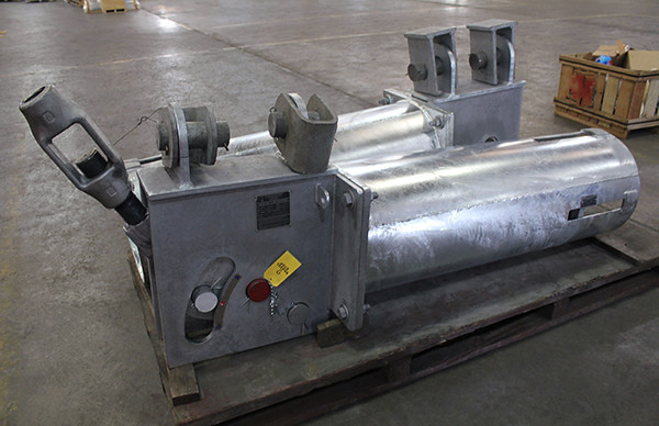
PT&P custom-designed U-type constant spring supports for an oil refinery in Texas. Constants can be utilized in refineries within blocks such as hydrogenation units, naphtha desulfurization units, and fluid catalytic crackers. The spring’s frame is manufactured from A36 carbon steel and hot-dipped galvanized to protect against corrosion. For instances where there was axial and lateral movement, 240 Gr. 304 slide plates were installed on the load flanges of the constants. The constants supplied are designed for an operating load ranging from 1,085 lb. up to 17,480 lb. and horizontal travel from 2.5” to 6”. The overall dimensions range in size from 17” H x 20” W x 31” L to 28” H x 26” W x 66” L. Load and travel tests per industry standards were performed prior to shipment.
PT&P Designed and Fabricated Variable Springs for a Refinery in Texas City
Type:
G-Type Variable Spring Support Assemblies
Design:
Operating Loads from 3000 lb. to 4000 lb.
Movement of 1”
Material:
Carbon Steel
Testing:
Load & Travel Test | Q.C. Inspection
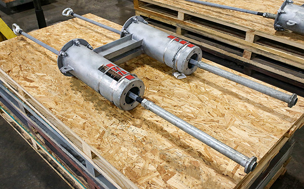
Pictured here is a Type G variable spring hanger assembly designed for an operating load up to 4000 lb. and 1” movement. This type of support assembly is formed by welding two standard spring assemblies to the ends of a pair of channels. The Type G assembly is especially adaptable for avoiding interference in spaces where the headroom is limited. The assemblies are fabricated from carbon steel and underwent spring load tests before shipment.
Constant Spring Supports Designed for LNG Service in Louisiana
Type:
B-Type Constant Spring Supports
Size:
11-5/8 W x 41” L x 19” H to 21” W x 88” L x 38” H
Material:
A36 Carbon Steel | Hot-dipped Galvanized
Design:
Operating Load Range: 3,170 lb. to 48,400 lb.
Movement of 3” to 8”
Testing:
Q.C. Inspection | Load and Travel Tests
PT&P manufactured B-type constant spring supports for LNG service in Louisiana. These constants are fabricated from A36 carbon steel with alloy steel 5160 spring coils. The constants are designed for an operating load range of 3,170 lb. to 48,400 lb., and movements from 3” to 8”. They range in size from 11-5/8 W x 41” L x 19” H to 21” W x 88” L x 38” H. To avoid delivery delay, a standard frame was paired with an oversized coil and coil housing. The lugs were rotated 90 degrees from the standard to allow the hanger to swing beyond +/- 4” of side-to-side swing. Standard load and travel tests were performed prior to shipment.
6-1/2 Foot Diameter Custom Insulated Sliding Pipe Shoes for HVAC Service at a Semiconductor Manufacturing Facility
Type:
Insulated Sliding Pipe Shoes
Size:
78″ NPS | 12″ L x 90″ H x 85″ D
Material:
HDG Carbon Steel | High-Density Calcium Silicate
Design:
+/- 3″ Axial & +/- 1″ Lateral Movements
Operating Loads up to 88,000 lb.
200°F Temperature Pipeline
Testing:
Q.C. Inspection | Visual & “Fit-Up” Tests
PT&P custom-designed insulated sliding pipe shoes for HVAC service at a semiconductor manufacturing facility. The shoes are fabricated from A36 carbon steel and hot-dipped galvanized for corrosion resistance, and include insulating material consisting of high-density calcium silicate. The insulated sliding shoes are designed for a 78″ pipe size with overall dimensions of 12” L x 90” H x 85” D to accommodate +/- 3″ axial and +/- 1 lateral movement at a pipeline temperature of 200°F. This design can accommodate operating loads of 88,000 lb., with each shoe weighing approximately 1,200 lb. Our quality control department performed visual and “fit-up” tests for this “Rush” shipment. *image shows product during assembly
Custom Technical Training Sessions – P.E. Credits
Boost Your Pipe Stress Engineering Expertise with PT&P Customized Virtual Training
While sometimes overlooked in the broad scope of equipment and engineering in an operating plant, Pipe Stress Engineering and knowledge of Expansion Joints and Spring Supports continues to be a sought after skill in industries dealing with high-temperature processes including Semiconductor, Oil and Gas, Chemical, and Power. PT&P’s customized virtual training options are offered free of charge and allow you and your team to develop these skills by having an understanding of the fundamentals of Pipe Stress Engineering and how the components used to manage Pipe Stress are designed, inspected, and maintained.
Piping Technology & Products would like to make sure we stay connected with key customers during this challenging time and find ways to continue supporting your business. While promoting social distancing measures to protect our employees and communities, we are offering online Zoom technical training sessions designed to benefit Engineers, Maintenance Planning, Reliability, Turnaround Planning, Vibration Inspection, and Operators/Technicians. The sessions count as PDH credit, and we offer training on a variety of topics, including the following:
Basics of Pipe Stress— Thermal expansion and methods of managing stress from thermal expansion
Spring Supports — Design of Spring Supports, Hot and Cold Settings, Appropriate use of travel stops
Dynamic Restraints — Applications of Sway Braces/Struts and design of Hydraulic and Mechanical Snubbers
Static Restraints— Types of Materials used for pre-insulated supports for insulation
Friction Solutions — Material selection for Slide Plates
Vibration Solutions — Solutions to reduce vibrations and noise, lowering maintenance costs
Expansion Joints — Overview of managing pressure thrust and squirming, types of movements, and movements supported by different types of expansion joints including Single, Universal, Hinged, Gimbal, Slip, and Fabric. Also includes an overview of the parts of the expansion joint and their purpose.
Please let us know what topic or combination of topics would be most useful to you and your team, and we would be happy to customize a training session for you. Would you be interested in participating? When would be a good time to set up a session?
Please let us know how we can be of assistance, and we hope you stay safe and have a wonderful day.
Fabricated Duct Work Transition Pieces for Polyethylene Dust in a Chemical Plant
Type:
Duct Work Transition Pieces
Size:
10” NPS | 15″ Length | 13-1/2″ SQ Flange End
Material:
Carbon Steel | 3-Coat Paint System
Test:
QC Inspections | 100% Dye-Penetrant Exam
Sweco Fab., a division of PT&P custom designed multiple duct work transition pieces for polyethylene dust at a chemical plant in Louisiana. The units are fabricated from carbon steel and include a 3- coat paint system on the outside, with a light grey finish. The dimensions are 15” length, 13-1/2” SQ flange end, and 10” NPS at the other end. Transition pieces are normally used to join duct work of dissimilar cross-sections and sizes. Media passing through the transition piece can be air, liquid, gasses, dust, dirt, chemicals, etc. Prior to shipment, each of the units underwent quality control inspections including 100% dye-penetrant examination.
Cold Insulated Supports at a Chemical Plant in Texas
Type:
Pre-Insulated Pipe Supports | Cold-Temperature
Size:
1/2″ -3″ Pipe Sizes | 4″ Thick Insulation
Material:
Polyurethane Insulation | HDG CS Jackets
Testing:
Q.C. Inspection & Tests
Pipe Shields, a division of PT&P, custom-designed multiple A6000U series insulated supports for a chemical plant in Texas for cold temperature piping. The cold pre-insulated shoes are fabricated from carbon steel with galvanized jackets, polyurethane foam insulation (PUF) and a vapor barrier. They are designed for pipe sizes ranging from 1/2” to 3” with insulation up to 4” thick. Standard quality control tests were performed prior to shipment. Learn more about our pre-insulated supports and place your order with us today!
Case Study: Emergency Spring Supports
PT&P often receives requests requiring responses in minutes. We have set up our operation to handle these situations and provide a high level of service to our customers. Key aspects of our Emergency Service include:
7/24 staffing by PT&P field engineer with 1-hour call back
6/24 production schedule with close integration between field engineering and production for emergency orders
A policy of providing technical assistance as necessary on all orders
The following is a timeline of PT&P’s response to an emergency request for variable springs at a major refinery:
5:56 PM – PT&P receives a request for immediate assistance through the online emergency form that notifies our field service team
6:07 PM – Initial call with the customer to go over the situation
7:00 PM – 9:30 PM – Detailed discussions between the field engineer and the customer, purchasing, engineering, and field supervision personnel
9:45 PM – Photos sent to the field engineer
9:45 PM – 10:15 PM – Field engineer makes design modifications
10:15 PM – Quote sent to the customer
10:30 PM – PO issued. PT&P field engineer collaborates on a production plan with the night production manager
12:00 AM – Confirmation of production schedule
1:55 AM – Hot Shot Transportation company picks up the shipment from PT&P
5:00 AM – Customer receives the product
PT&P supplied spring supports for a standard order where a list of spring supports was requested. At that time, it was not known that the specifications were incorrect. They found the issue while attempting to replace the spring cans during a turnaround.
While going through the new quote requested with revised specifications, the PT&P field engineer working on the emergency discovered some discrepancies. The customer was trying to order Type A spring cans, but the drawing indicated that it might require a C-type spring. The PT&P field engineer asked to verify the information and requested pictures of the spring supports, and the top and bottom attachments so that he could double-check himself. After approximately 1 hour, the PT&P engineer received pictures from the field, and as expected, the original information had several issues. Based on the pictures, the previous order, and provided drawings, our engineer made some important design changes. For example, one of the spring supports was on the lower end of the load range and while it would have worked, the spring support had a likelihood of future issues. As a result, the next size-up spring support was better suited.
There were more than 20 calls and messages between PT&P engineers and several people from the customer’s facility including purchasing personnel, the site engineer, and the field supervisor. This communication occurred between 7:30 and 9:30 PM.
The photos were provided to PT&P around 9:45 pm. The PT&P engineer sent a quote at 10:15 PM, and a P.O. was issued in the next 15 minutes. PT&P engineer coordinates with PT&P shop leadman and sends him all the details for fabrication, and the detailed shipping information was sent by 11:00 PM. The engineer later followed the progress around 12:00 AM. The material was ready and picked up by Hot Shot at 1:55 AM and got delivered at 5:00 AM.
The following is the e-mail we received from the customer just a couple of hours after receiving the shipment:
“Good Morning, I would like to take a minute to thank your Emergency team for all their effort and prompt response to our request on the evening of 02/27/2020. Your field engineer did an outstanding job of working through issues we had, he worked several hours with us to get our needs taken care of.
Again Thank you for an outstanding job!”
Case study on Custom Variable Design For Limited Spacing
Problem:
PT&P received an RFI on supporting a coker duct with a base type spring support, which has been supported by a shoe and a short concrete beam, resting on a long concrete beam that is part of the plant structure.
Customer finding:
The duct needs to move upward for proper running operation and to relieve stress buildup. This can only be done by using a spring support. The short concrete beam below the shoe is only 12” high. Supports found in the market can not fit in a 12” space for the load being applied by the duct. Adding extra structure around and above the duct, for a hanger spring support, is costly.
Data received:
Duct diameter: 42”
Cold load: 36294 lbs
Hot load: 30220 lbs
Movement: 1.94” upward
Spring rate desired: 3125 lb/in
Support Type: Base type
Space available between the bottom of the shoe and main supporting concrete beam: 12”
Solution devised by PT&P:
Since a single support cannot fit underneath the shoe, PT&P explored the possibility of fitting variable supports around the duct, on the supporting beam. When the customer relayed the surrounding dimensions to PT&P, it was decided to use two standard PT&P variable supports and bridge them by using a specially designed bridging assembly.
Keeping in mind that the hot load and movement are what is important to consider for the support assembly, the load and spring rate were split into two to find an appropriate variable spring support set. To keep the assembly as short as possible, a slighter stronger spring rate variable supports were selected that are still within the specs. We could still go to a lighter spring rate variable support. The side effect would be longer variable supports.
Pre-Insulated Support Solutions
PT&P offers the most extensive line of pre-insulated supports that leverages PT&P’s engineering capabilities in material science and structural engineering. We have custom-engineered many solutions using a combination of FEA, thermal analysis, and material engineering. View our pre-insulated support product archive gallery.
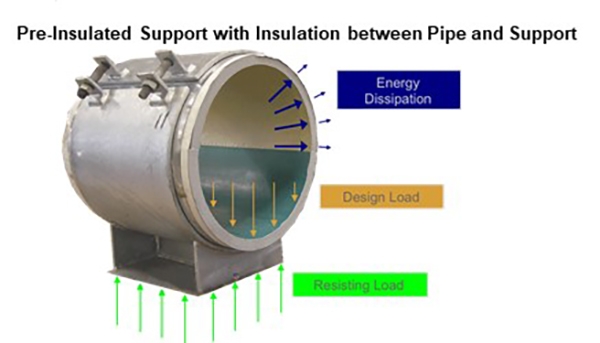
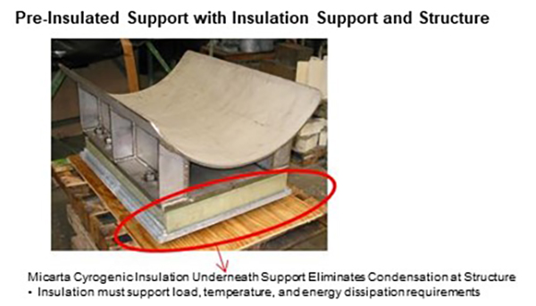
There are two approaches to pre-insulated shoes, as shown below. You can either insulate between the pipe and the pipe support or you can insulate between the pipe support and the structure.
Key design considerations on an overall design include:
Temperature limits which must be supported
Energy which must be dissipated
Ensuring condensation is not formed which would cause corrosion
Ensuring temperatures of exposed areas remain below maximum temperature allowed by plant safety
Cost of the design
Longevity of insulation supporting the required load, temperature, and energy dissipation
Allowable space for overall support
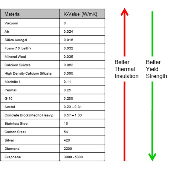
Insulating pipe supports is more challenging than insulating pipe. The reason is that pipe insulation is not required to bear the load of the pipe. With pipe support, the load of the pipe must be supported. The reason this is challenging is that insulation efficiency tends to be inversely related to compressive strength. The table below shows the k-value or thermal conductivity of a variety of materials.
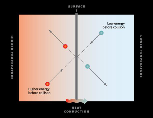
The challenge with insulation and compressive strength is that molecules are transmitters of energy. As the graphic on left below, collisions between molecules are what allow the transfer of energy. Hence, the density of molecules, in general, allows for greater transmission of thermal energy. This is why a vacuum is a perfect insulator as it offers no molecules which can be used to transfer thermal energy.
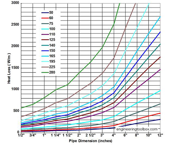
In addition to insulation limiting the thermal energy transferred to the pipe support or structure, exposed steel loses thermal energy to air. For example, the chart below heat loss from steel pipe based on the pipe dimension and temperature difference between the pipe and air. Under MSS code, steel supports lose 100° F per inch as measured from the outer wall of the pipe.
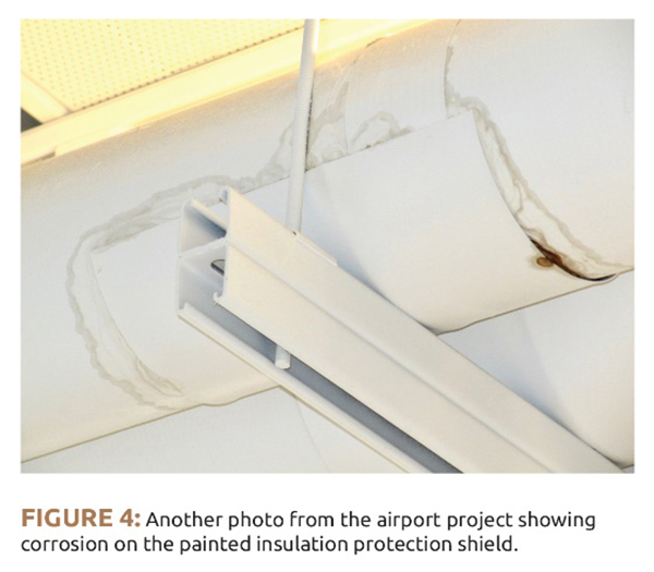
Below is a photo of corrosion due to condensation at a support location. This is an example of the issues that can arise when insulation is not properly engineered.
PT&P offers a complete range of capabilities for insulation, including:
Pre-Insulated Supports – PT&P is the global leader in pre-insulated supports for both hot and cold applications.
Custom Pipe Support Design – PT&P can custom-design pipe supports, taking into account structural issues, space limitations, special material requirements, and management of thermal issues.
Case Study #1
PT&P received the cryogenic pipe support design from a major EPC for a large LNG project. After receiving the design, PT&P became concerned with the performance of the design based on its experience with cryogenic pipe supports. Our engineers ran FEA and thermal analysis, which showed the design would meet the requirements for the project. PT&P set up and executed a cryogenic test at its facility and reviewed its calculations with the customers. Based on this feedback, the customer changed the support design for a multi-billion-dollar project.
Case Study #2
PT&P was requested by a customer to determine the optimal insulation choice and thickness for a chilled water line. PT&P provided the customer with a range of potential options for insulation. Once the customer had determined their insulation preference, PT&P ran the calculations to determine the required insulation thickness for the line.
Firetemp® Insulation | HDG CS | SS on Polyethylene
Testing:
Q.C. Inspection & Tests
PT&P custom designed pre-insulated sliding pipe shoes with FRP lining for high-temperature pipelines in Ohio. The “hot shoes” are 15” long, range in diameter from 1-1/2” to 3” and are designed for a B.O.P. of 4”. The shoes are designed with Firetemp® insulation for temperatures up to 1800°F. The supports are fabricated from carbon steel with a hot-dipped galvanized finish and include stainless on polyethylene slide plates. A visual inspection was performed prior to shipping.
Case Study: Fig. 1400 Pipe Shoe Solution for Vibration in Piping
Problem:
PT&P received an RFI from a chemical plant with excessive vibration in the piping in the rack which resulted in breaking the shoe supporting the trunnion at the pipe elbow.
They approached PT&P for their expertise in resolving vibration problems and for a recommendation of the appropriate pipe support for this solution.
The plant experienced the vibration issue on the pipe for some time and wanted to resolve and eliminate the vibration permanently.
Pipe Shoe supporting a trunnion front view
Pipe Shoe supporting a trunnion side view
The engineer at the plant recommended using a Fig. 11 skid shoe similar to the broken shoe in the picture with additional gussets.
There is a space limitation under the trunnion and can accommodate only a shoe type support.
PT&P recommended using one of their most sturdy clamped shoe, a specially fabricated fig. 1400 pipe shoe lined with a lamination of Siltemp®-Fabreeka-Siltemp® or a lamination of Neoprene-Fabreeka-Neoprene, depending on the temperature the trunnion is exposed to.
Another solution that most definitely works for eliminating the vibration problems in piping is using Hold Down clamps for pipe shoes lined with lamination of Siltemp®-Fabreeka-Siltemp® or a lamination of Neoprene-Fabreeka-Neoprene depending on the temperature the line is exposed to.
Siltemp® can withstand continuous temperature up to 1,800oF. Neoprene can be used for a temperature range of -50oF to 275oF. Fabreeka is good for a temperature range of -65oF to 200oF.
In this particular case, however, the Fig 1400 clamped shoe is a better option considering the gap between the trunnion and the structure on which the support would be resting.
Examples of PT&P supplied supports for Vibration Problems:
Example 1.
PT&P designed and manufactured custom elevated pipe shoe-clamp supports for part of a palletizer transfer line in a polymer plant. The custom supports were designed to prevent cracking in the welds and grout base due to severe vibration in the line. The assemblies have an overall height of 48″ with an adjustable load column. The clamp-shoes are 13″ wide by 14″ long and designed for a 12″ diameter aluminum pipe. The assemblies are carbon steel with a hot-dipped galvanized finish and include a unique laminated vibration-dampening lining for the clamp.
Example 2.
The 54” suction line carrying gas to the turbine at a rate of 1.7 million lb. per hour developed a severe vibration in the line. The deflections in the line were up to ¾” and it was fully observable during operation.
PT&P designed and manufactured a special elevated hold-down clamp, including a unique laminated vibration-damping lining. The entire assembly stands 22’ high and is coated with a carboline zinc finish.
After installation and resumption of operations, the vibrations are now almost imperceptible.
Summary:
Most of the time, vibration in the line is for multiple reasons and not really associated with the stresses in piping. It might be because of some misalignment or due to the flow dynamics of the line content. However, in a majority of the cases, the vibrations can be alleviated by using adequate hold-downs or by use of proper supports. The surest first step is to assess the line routings and configurations, and determine the types of supports and that they are all located appropriately.
For vibrations associated to pump cavitation or believed to be originating from equipment, a detailed vibration analysis will be a better option to go with. PT&P has the expertise to perform a basic vibration analysis during a dynamic stress analysis using CAESAR software. Many of the times it is initially found to be most likely attributable to flow conditions. Of these, some require extensive flow analyses undertaken by a qualified process engineer; often a costly process.
However, we are also aware that many vibration problems can be resolved by the application of good engineering practices and empirical engineering methods. These together with augmentation of an existing design can resolve the problems at a more moderate cost.
PT&P has performed several remediations of piping manifesting severe vibrations and associated line displacements. All of the remedial actions recommended, and taken, so far have been successful. All the solutions were derived through empirical methods, and custom-designed clamps were utilized with special vibration dampening linings. For those scenarios, no vibration analyses were performed, nor deemed necessary to arrive at completely satisfactory solutions. PT&P has had considerable success with these approaches.
FRP Wear Pads with Epoxy Adhesive Supplied for LNG Service
Type:
FRP Wear Pads
Size:
2″ – 4″ Dia. | 6″ – 12″ Long | 1/2″ Thick
Material:
Vinyl Resins
Testing:
Standard Visual and Dimensional Tests
PT&P fabricated 160 FRP wear pads for an LNG facility in the Caribbean. The wear pads are for pipes ranging from 2” to 4” in diameter 6” to 12” long and 1/2” thick. They are fabricated from vinyl resins and are designed for operating temperatures up to 400°F. The FRP pads are secured to the pipe using an epoxy adhesive to protect the uninsulated pipe from the support structure. Standard visual and dimensional tests were performed prior to shipment.
Wireless Technology & Bluetooth Tracking Webinar
** Turn up your speakers to hear the audio. Please be patient as the screen will become visible shortly after the speaker begins the presentation. You may click the monitor icon below each video to view the webinar in full-screen mode.
NOTE: PDH credits are NOT offered for our recorded webinars.
Pipe Support Selection & Design Influences Webinar
** Turn up your speakers to hear the audio. Please be patient as the screen will become visible shortly after the speaker begins the presentation. You may click the monitor icon below each video to view the webinar in full-screen mode.
NOTE: PDH credits are NOT offered for our recorded webinars.
Pipe Support and Expansion Joint Inspection Best Practices Webinar
** Turn up your speakers to hear the audio. Please be patient as the screen will become visible shortly after the speaker begins the presentation. You may click the monitor icon below each video to view the webinar in full-screen mode.
NOTE: PDH credits are NOT offered for our recorded webinars.
Piping Engineering Training – The PT&P Process Webinar
** Turn up your speakers to hear the audio. Please be patient as the screen will become visible shortly after the speaker begins the presentation. You may click the monitor icon below each video to view the webinar in full-screen mode.
NOTE: PDH credits are NOT offered for our recorded webinars.
Nano Constant Performance Test
See PT&P’s performance testing of our Nano Constant.
Pipe Stress Analysis Case Study – Pump Discharge
Problem:
A chemical plant approached PT&P about the need for an expansion joint which was required as part of a replacement of pumps and the addition of new pump discharge piping. As we started discussing the requirements, the client became concerned about whether the stress analysis they had conducted had properly specified the correct layout and expansion joint. The client used an expansion joint in their analysis on the vertical piping coming out of the pump nozzle.
The client requested a quote from PT&P to perform a stress analysis to determine the proper specification of the expansion joint and overall line. The client had limited space availability. PT&P provided a quote of <$10K for the stress analysis and expansion joint specification to be completed by:
Pipe stress engineer with 30+ years of experience and former Secretary of Texas Society of Professional Engineers
Expansion joint engineering lead with over 30 years of experience
Fig: Iso Drawing for Pump Discharge piping
Input Data:
Operating Temp – 245oF; Operating Pressure – 150 psi; Steam Out Temp – 285oF; 12” SS A312 TP304 Pipe; 2” Insulation thickness; Specific gravity – 0.944; API 610 allowable nozzle loads
Challenges:
CAESAR treatment of expansion joints is much simpler than pipe supports. Various spring rates are input for the expansion joint along with information about tie rods. This allows CAESAR to utilize the spring rates to calculate thermal growth movements that will be absorbed by the lower spring rate of the expansion joint vs other components of the piping system. It does NOT calculate whether forces from thermal growth will cause excess stress on the expansion joint. For example, expansion joints are not designed to absorb significant torsional force. Proper design of piping systems with expansion joints requires both system expertise in pipe stress engineering as well as component-level expertise in expansion joints. PT&P is uniquely positioned to help customers as we have been doing pipe stress engineering and expansion joint design and manufacturing for over 40 years.
Solution:
PT&P reviewed the CAESAR model from the client and determined that there was excess torsional force on the expansion joint in the customer design. In addition, the placement of the expansion joint on the vertical line would require an in-line pressure balanced expansion joint which is more expensive and requires maintenance of 3 bellows. NOTE: If an in-line pressure balanced expansion joint was not used, the force of pressure thrust would be placed on the pump which would cause excess force at the system operating pressure of 150 PSI.
PT&P tried reducing the loads at the piping by eliminating the expansion joints, however, the loads were very high without the expansion joints. PT&P tried using the expansion joints in the horizontal piping coming out of the pumps, but the available spacing was not sufficient to fit in an expansion joint on one of the lines. PT&P worked with the client to change the elbow on the line from a long radius to a short radius thus providing sufficient space for the expansion joint in the horizontal piping.
With deep expansion joint expertise, PT&P was able to provide the client with exact space requirements with a space-optimized design. In this case, PT&P designed a 2 PLY Inconel 625LCF expansion joint with a bellows convolution layout which minimized the length of the expansion joint.
On performing the stress analysis using the expansion joint, the stress code passed for the piping and the loads were within the allowable ranges, however, there was a high moment about one axis (Mz) causing a concern.
Fig: CAESAR model for piping with EJ at pump discharge horizontal piping
Node
FX lb.
FY lb.
FZ lb.
MX ft. lb.
MY ft. lb.
MZ ft. lb.
Restraint Type/Tag
10
545
-121
189
1720.1
-361.4
-2676.3
TYPE=Rigid ANC
21
545
-121
189
1341.5
-629.6
-1757.6
TYPE=Rigid ANC
70
0
-2471
0
0.0
0.0
0.0
TYPE=Prog Design VSH
180
794
-4123
-1446
0.0
0.0
0.0
TYPE=Rigid +Y
185
238
-1291
-458
0.0
0.0
0.0
TYPE=Rigid +Y
240
-0
-2954
-1182
0.0
0.0
0.0
TYPE=Rigid +Y
246
-605
-2470
-429
0.0
0.0
0.0
TYPE=Rigid +Y
247
-88
0
0
0.0
0.0
0.0
TYPE=Rigid GUI
247
0
0
38
0.0
0.0
0.0
TYPE=Rigid LIM w/gap
247
-0
-2625
788
0.0
0.0
0.0
TYPE=Rigid +Y
270
-892
-211
-236
-932.4
117.3
8247.0
TYPE=Rigid ANC
281
-892
-211
-236
-460.5
451.6
6164.4
TYPE=Rigid ANC
330
0
-2197
0
0.0
0.0
0.0
TYPE=Prog Design VSH
2130
0
-579
0
0.0
0.0
0.0
TYPE=Rigid +Y
2130
0
0
2890
0.0
0.0
0.0
TYPE=Rigid Z
Allowable
-900
700
1100
2700
1300
2050
Fig: CAESAR output indicating high moment Mz along one axis on one pump
PT&P worked with the client to modify the piping by:
Adding a loop to the horizontal piping
Adding an expansion joint on the pump discharge horizontal piping
Adding a spring support at the top of the pump discharge vertical piping
With these changes, the design passed the stress codes in the pump discharge piping and kept the loads at the nozzle within the allowable range.
Fig: Modified piping with loop on the horizontal discharge pipingFig: CAESAR model for modified discharge piping with EJ at pump discharge horizontal piping
Node
FX lb.
FY lb.
FZ lb.
MX ft. lb.
MY ft. lb.
MZ ft. lb.
Restraint Type/Tag
10
402
-121
324
2931.4
-619.0
-1972.3
TYPE=Rigid ANC
21
402
-121
324
2283.8
-1077.8
-1340.0
TYPE=Rigid ANC
70
0
-2692
0
0.0
0.0
0.0
TYPE=Prog Design VSH
180
661
-3502
-1235
0.0
0.0
0.0
TYPE=Rigid +Y
185
208
-1040
-360
0.0
0.0
0.0
TYPE=Rigid +Y
240
-21
-3065
-1226
0.0
0.0
0.0
TYPE=Rigid +Y
246
-603
-2455
-422
0.0
0.0
0.0
TYPE=Rigid +Y
247
-93
0
0
0.0
0.0
0.0
TYPE=Rigid +GUI
247
0
0
78
0.0
0.0
0.0
TYPE=Rigid LIM w/gap
247
-0
-2629
789
0.0
0.0
0.0
TYPE=Rigid Y
270
-455
-141
-43
1268.8
-2276.7
2319.5
TYPE=Rigid ANC
281
-455
-141
-43
1354.7
-2215.8
1210.1
TYPE=Rigid ANC
330
0
-2858
0
0.0
0.0
0.0
TYPE=Prog Design VSH
2120
0
-1457
0
0.0
0.0
0.0
TYPE=Rigid +Y
2170
0
0
0
0.0
0.0
0.0
TYPE=Rigid +Y
2170
0
0
2178
0.0
0.0
0.0
TYPE=Rigid Z
Allowable
900
700
1100
2700
1300
2050
Fig: CAESAR output indicating loads and moment within allowable range
Summary:
PT&P offers an exceptional value for a class of problems that are often not well served – small capital projects. In this case, the customer’s budget did not allow for the funding typically required to engage consulting experts with deep pipe stress and expansion joint design and engineering expertise. If the customer had proceeded with the original design, they would have likely suffered from ongoing maintenance issues on expansion joint and pump.
PT&P is able to effectively serve small capital projects because it does not carry the overhead of a traditional professional services firm. We have 70+ design engineers on staff and a sales organization for our manufacturing business. This allows us to engage on small projects without having to keep dedicated consulting staff and trying to manage utilization rates for this staff.
While PT&P does not have the range of expertise of a typical engineering firm, we have extraordinarily deep expertise in piping. This allows us to put world-class experts on small projects. In this case, it allowed us to place a pipe stress engineer and expansion joint engineer who each had over 30 years of experience on a very small project that cost the customer <$10K. This experience was highly valuable on this project as CAESAR does not “guide” a pipe stress engineer into a proper overall system design incorporating expansion joints.



 In addition to insulation limiting the thermal energy transferred to the pipe support or structure, exposed steel loses thermal energy to air. For example, the chart below heat loss from steel pipe based on the pipe dimension and temperature difference between the pipe and air. Under MSS code, steel supports lose 100° F per inch as measured from the outer wall of the pipe.