How PT&P Repaired Another OEM’s 20,000 lb Constant Spring Hangers in 2 Days During an Active Turbine Outage
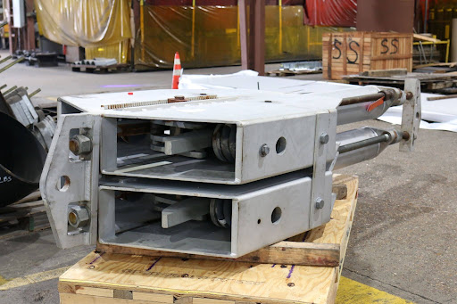
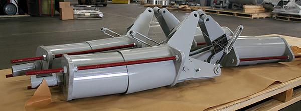
When an active turbine outage required immediate action, PT&P repaired and refurbished two constant spring hangers designed to support 20,000-pound loads each, originally manufactured by another OEM.
Emergency Repair of Two Constant Spring Hangers at PT&P
Background
A major midstream operator experienced the failure of two large constant spring hangers during a planned turbine outage. Each unit was rated at a 20,000 lb load capacity with 27 inches of travel, serving as critical pipe supports in high-load applications.
Piping Technology & Products (PT&P) has maintained a field services relationship with this customer since 2017–18, when PT&P engineers first surveyed the units onsite. The first repair was completed in 2019. This project marked the fourth repair PT&P has performed on this type of unit for the same customer.
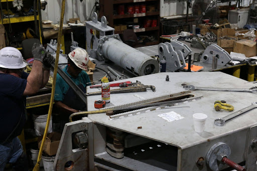
Disassembly & Inspection
The Challenge
The failure occurred under the most demanding conditions possible: an active outage with a fixed window for completion.
Active Outage & Fixed Timeline – The turbine outage was underway, and every day the hangers remained out of service extended downtime risk. A rapid repair-and-return solution was essential.
OEM Lead Time of 4 Weeks – The original equipment manufacturer quoted a 4-week turnaround, a timeline incompatible with the outage schedule. The customer needed a partner who could move immediately.
Repeat Failures on Critical Units – The units have required repeated repair over the years, with suspected causes including manufacturing defect, excessive load, and general wear. Each failure places the same critical supports back at risk.
High-Capacity & Long-Travel Units – At 20,000 lbs capacity and 27 inches of travel, these are large, engineered supports. Repair requires disassembly, component-level rebuild, calibration, and load verification, not a routine shop job.
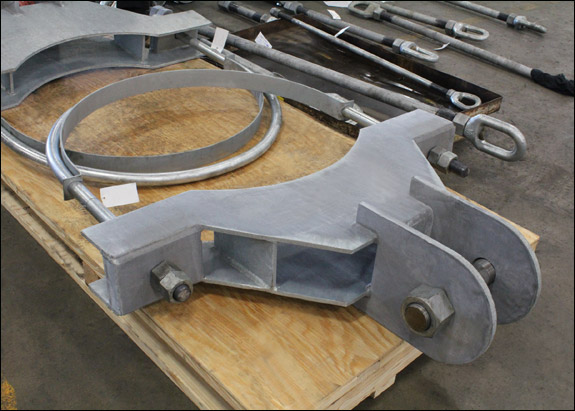
Component Repair & Rebuild
The Solution
PT&P accepted the job and executed a complete repair-and-return cycle in 2 business days.
Disassembly & Inspection:
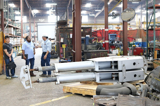
Full teardown of both units upon arrival at PT&P’s Houston facility
Component-level inspection to identify damaged and worn parts
Assessment of spring coils, linkages, and load-bearing components
Component Repair & Rebuild:
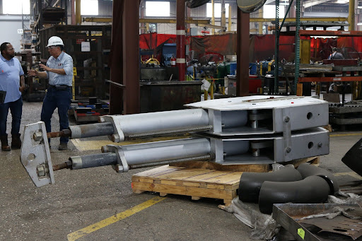
Repair and replacement of damaged components
Complete rebuild of both units
Restoration to original load and travel specifications
Quality Control & Assembly:
Final assembly and QC verification
Load and travel verification against the 20,000 lb / 27″ rated specifications
Units certified and prepared for immediate return shipment
Shipment:
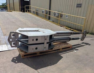
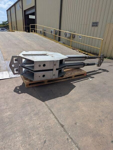
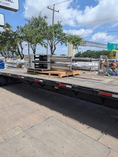
Both units shipped in 2 business days after receipt, allowing reinstallation within the outage window
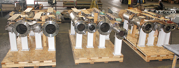
Packaged & Ready to be Shipped
Results
2 units repaired and returned to service within the outage window with speedy turnaround time through PT&P’s rapid turnaround capabilities.
20,000 lb capacity and 27″ travel fully restored on both units
2-day turnaround against the OEM’s 4-week quote
4th successful repair for this customer since 2019
Ongoing relationship spanning field survey, onsite visits, and repeat repairs since 2017–18
Facing an Emergency or Turnaround Deadline?
PT&P repairs spring supports regardless of original manufacturer, with engineering, fabrication, and testing in-house at our Houston, TX facility. For urgent repair requirements, contact PT&P’s 24×7 emergency line.
Hot-Dip Galvanizing (Substance) VS Powder Coat or Paint (Style)
One of the most surprising findings from PT&P’s extensive experience conducting more than 1,000 plant audits is the frequency of corrosion problems associated with painted and powder-coated pipe supports. While paint and powder coating can provide an attractive finish and a wide range of color options, appearance often comes at the expense of long-term corrosion protection.
In many industrial environments, the choice between paint and hot-dip galvanizing (HDG) is not simply a cosmetic decision—it is a decision that can significantly affect equipment reliability, maintenance costs, and service life.
PRODUCT LINEUP
Pipe supports, spring hangers, expansion joints, all engineered to specifications
Figure 1 – Pictures of New Galvanized Pipe and Painted Steel Pipe
Figure 2 – Pictures of 25-Year-Old HDG Support VS. 8-Year-Old Painted Support
PT&P Hot-dipped Galvanized Support
25 Years In-Service in Dubai – Salt Air from
Persian Gulf – 100 Sandstorms per Year
NON-PT&P Painted Support
8 Years In-Service in Texas
Salt Air From Gulf Coast
When Paint May Be Appropriate
Although hot-dip galvanizing is generally the preferred solution for structural steel and pipe supports, paint does offer advantages in certain applications:
When aesthetics and color selection are important
When working with thin-gauge steel that may distort during galvanizing
When minimizing initial cost is the primary objective
When galvanizing is impractical due to component size or configuration
However, these advantages should be weighed against the increased maintenance and reduced service life often associated with painted systems.
PT&P Hot-dipped Galvanized Support
25 Years In-Service
NON-PT&P Painted Support
8 Years In-Service in Louisiana
The most important distinction between the two protection methods lies in how they protect the steel.
Paint and Powder Coating: Barrier Protection
Paint and powder coating function solely as barrier coatings. They create a physical layer that separates the steel from moisture and oxygen in the environment. As long as this barrier remains intact, corrosion is minimized.
However, if the coating is scratched, chipped, or damaged during transportation, installation, maintenance, or normal plant operation, moisture can reach the steel surface and corrosion begins. Once corrosion starts beneath the coating, rust can spread and lift the paint away from the surface, accelerating deterioration.
Hot-Dip Galvanizing: Barrier and Cathodic Protection
Hot-dip galvanizing provides both barrier protection and cathodic protection.
During the galvanizing process, molten zinc reacts metallurgically with the steel surface to create multiple alloy layers consisting of zinc and iron. This is not simply a coating applied to the surface—it is a metallurgical bond between the zinc and steel.
More importantly, zinc acts as a sacrificial anode. Because zinc gives up electrons more readily than steel, it corrodes preferentially and protects the underlying steel from corrosion. Even if the galvanized surface is scratched or damaged, the surrounding zinc continues to protect exposed steel through cathodic action.
This sacrificial protection is a key advantage that paint and powder coating cannot provide.
Any coating which provides a barrier to the moisture and oxygen in the air will help protect carbon steel from corrosion. A properly painted surface will provide a barrier, but it is subject to scratching from contact with hard objects.
Figure 3 – Picture of Thin Gauge Steel Better Suited to Painting
Any coating which provides a barrier to the moisture and oxygen in the air will help protect carbon steel from corrosion. A properly painted surface will provide a barrier, but it is subject to scratching from contact with hard objects.
Figure 4– Illustrates how rust can grow and damage a painted surface when corrosion begins because the paint barrier is broken by a scratch.
Figure 5 – HDG vs Organic Coatings (from German Technical Presentation)
Source: Conference Paper on Galvanizing of highway and railway bridge constructions for Dynamic Loads (Germany) by M.Oechsner Technische Universität Darmstadt, Fabrian Simonsen EJOT Tambach GmbH, Dieter Ungermann Technische Universität Dortmund, Dennis Rademacher ArcelorMittal Europe.
Figure 6 indicates how corrosion damages carbon steel. Note that the pitted area to the right is anodic and gives up electrons while the cathodic area to the left (where water and oxygen from the air are present) is where rust appears. The pitted area where the carbon steel is weakened is not where the rust appears.
Zinc has a greater tendency to give up electrons than carbon steel, so when both are present, zinc becomes the anode and protects the carbon steel.
Figure 7 indicates corrosion with the zinc giving up the electrons and becoming pitted while the carbon steel remains undamaged. From this, we see that a zinc coating will protect carbon steel by “sacrificing” itself until the zinc is depleted. The rate of zinc depletion is relatively slow when the pH of the electrolyte is between 4 and 13.
HDG Corrosion Benefits
The following are the benefits of HDG for corrosion protection:
Abrasion Resistance – HDG is not one layer of coating but actually 4 layers of coating with different properties and different combinations of zinc and steel. The top layer is 100% Zn with a 70 DPN harness. Each layer closer to the base steel has an increasing level of hardness all the way to the Gamma Layer which is 75%Zn, 25% Fe and has a hardness of 250 DPN which is harder than the base steel which has a 159 DPN hardness.
Figure 8 – Layers of Hot-Dip Galvanizing and Associated Hardness
Cathodic Protection – A protection aspect of HDG that cannot be replicated with a simple coating such as paint is the cathodic protection of zinc. Salt water acts as an electrolyte between zinc and steel in an electrochemical circuit with zinc acting as the anode and steel as the cathode. As a result, steel is protected from corrosion until the Zinc is fully consumed. This means even exposed steel will be protected from corrosion by the zinc around the steel. Cathodic protection is important enough to be required on some Piping systems by Federal code.
Figure 9 – Cathodic Protection of HDG VS Paint
Below are examples of a painted pipe support with initial corrosion due to lacking cathodic protection, and a picture of deterioration once the initial corrosion has taken hold. As you can see, any pinhole, scratch, or nick will set off a corrosion process. Our experience has been from the time of manufacture, many areas are vulnerable to some damage to the surface coat during either construction or post turnover. This is devastating for a painted finish.
Figure 10 – Real World Example of Paint and Lack of Cathodic Protection
At Piping Technology and Products Inc., many customers have returned painted variable and constant spring supports which could no longer function due to corrosion. Costs must be considered during the specification of coatings for pipe supports. The owner and operator of a facility should consider life-cycle costs. Pipe supports are usually a relatively small percentage of the total cost of installing and operating a power plant, petrochemical plant, paper mill or other major facility. The small additional cost of hot-dip galvanizing the carbon steel components of pipe supports is most always a wise investment.
Figure 11 – Real World Examples of HDG VS. Paint / Lack of Cathodic Protection
PT&P Spring Support: 25 Years and Still In ServiceNON-PT&P Spring: 8 Years
Zinc Patina – As zinc is initially exposed to moisture, it reacts with water to form a porous layer of Zinc Hydroxide. As the material dries, it converts to a thin layer of zinc carbonate that is a passive, stable film that is not water soluble. The process of zinc patina formation takes approximately 6-12 months from the time of hot-dip galvanizing. This layer of zinc patina turns matte gray in color and significantly slows the rate of corrosion. The zinc patina is one of the reasons that the salt spray test is a very poor indicator of the benefit of galvanizing as keeping galvanized material wet does not allow for the formation of zinc patina.
Figure 12 – Formation of Water Insoluble Zinc Carbonate Surface Layer
Summary
Hot-dip galvanizing is generally the superior corrosion protection system for carbon steel pipe supports and structural steel components. Unlike paint and powder coating, galvanizing provides both barrier protection and sacrificial cathodic protection, allowing it to continue protecting steel even when the surface is damaged.
While paint remains useful for applications involving thin-gauge materials or where appearance is a primary consideration, facility owners and operators should evaluate corrosion protection methods based on total life-cycle cost rather than initial purchase price alone.
For most industrial pipe support applications, hot-dip galvanizing remains one of the most effective and economical long-term corrosion protection solutions available.
Custom Designed Constant Spring Supports for a Chemical Plant in Singapore
Type:
Constant Spring Supports
Size:
15-¼” W x 17″ H x 46″ L with 9-¼” OD
Material:
Carbon Steel | Hot-dipped Galvanized
Design:
2,379 lb. Load | 10″ Upward Movement
Piping Technology & Products (PT&P) custom-designed and manufactured constant spring supports for a chemical processing facility in Singapore that produces industrial gases such as hydrogen, carbon monoxide, and synthesis gases.
The constant spring assemblies were fabricated from ASTM A36 carbon steel and incorporated alloy steel coil springs. Each unit measured 15¼ inches wide × 17 inches high × 46 inches long with a 9¼-inch outside diameter. The supports were designed to carry an operating load of 2,379 lbs. while accommodating 10 inches of upward movement.
To meet the project’s specific requirements, the constants were engineered with telescoping spring coil housings, allowing the units to accommodate significant travel while maintaining a compact overall design. The assemblies were also coated with a protective paint system to enhance corrosion resistance and extend service life in the operating environment.
Prior to shipment, each constant spring support underwent PT&P’s standard load and travel testing procedures to verify performance and compliance with design requirements. As part of the company’s quality assurance program, every constant spring support manufactured by PT&P is tested before shipment. PT&P maintains an ISO 9001:2015 Quality Management System certified by DNV, ensuring consistent product quality and traceability.
PT&P manufactures more than 1,500 constant spring supports annually, with designs ranging from standard applications to highly customized units capable of supporting loads exceeding 150,000 lbs., and accommodating movements greater than 48 inches.
Constant spring supports are widely used in facilities where significant thermal expansion and contraction occur. Typical applications include crude distillation units (CDUs), hydrocracking units, residual fluid catalytic cracking (RFCC) units, naphtha hydrotreaters, hydrodesulfurization units, sulfuric acid regeneration (SAR) units, LNG facilities, geothermal plants, coker units, heat recovery steam generators (HRSGs), chemical processing plants, and other high-temperature industrial systems.
Unlike variable spring supports, constant spring supports are designed to maintain a nearly constant supporting force throughout the entire range of travel. Using one or more spring coils and a mechanical balancing mechanism, they accommodate vertical thermal movement while minimizing load variation on the piping system, thereby reducing stress on connected equipment and structures.
PT&P has developed its manufacturing capabilities to provide extensive customization options with minimal impact on delivery schedules. In addition to standard configurations, constant spring supports can be customized for materials of construction, protective coatings, dimensions, loads, travel ranges, load adjustments, and travel stop configurations.
PT&P REF. ORIGINAL POST 12112018
Understanding Pipe Stress Analysis for Safe and Reliable Piping Systems
Industrial piping systems operate under constantly changing conditions. Pressure, temperature fluctuations, vibration, weight, thermal expansion, and external loads all influence how a piping system behaves throughout its operating life.
While piping may appear stationary, it is continuously responding to operating conditions. As systems heat up, cool down, start up, or shut down, the piping expands, contracts, and transfers loads throughout the system. When these movements and forces are not properly evaluated, they can create a range of operational challenges, from excessive stress and vibration to support failures and unplanned downtime.
This is why Pipe Stress Analysis (PSA) plays such a critical role in modern piping system design.
The Purpose of Pipe Stress Analysis
Pipe Stress Analysis provides the engineering foundation for designing piping systems that are safe, reliable, and efficient. By evaluating how a system will respond under actual operating conditions, engineers can better understand:
System movement and flexibility
Load distribution throughout the piping network
Interactions between piping and connected equipment
Potential areas of concern before installation or operation
These evaluations are typically performed using industry-leading software that helps engineers model real-world operating conditions. Rather than reacting to problems in the field, PSA enables engineering teams to address them during the design phase, thereby improving overall system performance while reducing operational risk.
Supporting Better Engineering Decisions
Beyond identifying potential stress concerns, Pipe Stress Analysis helps engineers optimize piping systems early in the project lifecycle.
By evaluating piping layouts, support configurations, system flexibility, and load paths, engineers can make informed decisions that support both performance and constructability.
The result is a more efficient design process that can help:
Reduce unnecessary supports
Minimise field modifications
Improve constructability
Enhance overall system performance
These benefits contribute directly to improved project execution and long-term operational reliability.
The Connection Between Stress Analysis and Pipe Supports
One of the most important outcomes of Pipe Stress Analysis is determining how a piping system should be supported.
Pipe supports are not selected based on preference or convenience. Their location, type, and function are developed based on the analysis results and the system’s movement characteristics.
The analysis helps engineers determine where support solutions such as guides, anchors, spring supports, restraints, and other specialised configurations may be required to manage movement while maintaining system flexibility properly.
Because of this relationship, properly engineered pipe supports play a direct role in:
Maintaining piping system reliability
Protecting connected equipment
Supporting long-term operating performance
Preserving overall system integrity
Applications Across Multiple Industries
Pipe Stress Analysis is widely applied across industries where piping systems operate under demanding conditions.
Common applications include:
Oil & Gas
Petrochemical
Power Generation
Pharmaceutical
Process Plants
Data Centers
Industrial Construction
The value of Pipe Stress Analysis extends beyond stress engineers alone. Project managers, EPC firms, contractors, procurement teams, and facility owners all benefit from a clearer understanding of how piping systems will perform throughout their service life.
Supporting Compliance and Reliability
In addition to improving system performance, Pipe Stress Analysis helps ensure compliance with applicable industry codes and standards, including ASME, API, and other governing design requirements commonly used throughout industrial facilities.
Meeting these requirements is an important part of maintaining system safety, supporting operational performance, and ensuring long-term serviceability.
Value Beyond New Construction
Although Pipe Stress Analysis is commonly associated with the design and construction phase of a project, its value extends well beyond new installations.
For operating facilities, PSA can be used to evaluate modifications, investigate recurring issues, and identify the root causes of problems, such as:
Excessive vibration
Thermal movement concerns
Recurring support failures
Equipment loading issues
This insight allows facility teams to better understand system behaviour and make informed decisions when addressing operational challenges. For those responsible for day-to-day facility performance, understanding why pipe stress analysis matters for plant operations can help support safer and more reliable system management.
Closing Lines
Pipe Stress Analysis is far more than a design calculation. It is a critical engineering evaluation that influences piping system safety, reliability, support design, and long-term performance.
By providing a deeper understanding of how piping systems respond to real-world operating conditions, PSA helps engineers make informed decisions that support both project success and operational reliability.
With extensive experience supporting a wide range of industrial applications, PT&P continues to provide engineered piping and pipe support solutions backed by practical analysis and real-world operating experience.
Nominal Insulation Table (Size vs. Actual)
Understanding Pipe Insulation Sizes and Dimensions
This technical bulletin serves as a practical guide to pipe insulation sizing, helping engineers, designers, contractors, and maintenance personnel understand the difference between nominal pipe sizes, actual pipe dimensions, and insulation thickness requirements.
A common source of confusion in piping systems is that both pipe and insulation are often specified using nominal dimensions rather than their actual physical measurements. For example, a pipe designated as NPS 2 (Nominal Pipe Size 2) does not have an outside diameter of exactly 2 inches. Instead, it has an actual outside diameter of 2.375 inches. Likewise, a specified insulation thickness refers to the radial thickness of the insulation and not its overall outside dimension.
Our detailed pipe insulation size chart provides the dimensional information needed to properly match insulation thicknesses with the correct pipe outside diameters. This ensures proper fit-up, minimizes installation issues, and helps maintain the thermal performance of the insulation system.
Because the piping industry relies on terms such as Nominal Pipe Size (NPS) and Nominal Insulation Thickness, selecting insulation for a given pipe size often requires verifying the actual pipe outside diameter. For example, ordering insulation for a 2-inch pipe requires knowledge of the pipe’s true outside diameter to ensure a secure and properly fitted insulation assembly.
Similarly, when selecting insulation for smaller pipe sizes, such as 1¼-inch pipe insulation, it is important to verify dimensions using a steel pipe size chart or pipe outside diameter table. Confirming the relationship between the insulation inside diameter (I.D.) and the pipe outside diameter (O.D.) helps prevent excessive gaps or improper fit, both of which can reduce thermal efficiency, increase energy loss, and potentially contribute to moisture intrusion and corrosion under insulation (CUI).
Understanding these dimensional relationships is essential for designing and installing effective insulation systems that provide long-term thermal performance, energy conservation, and mechanical reliability.
NOMINAL INSULATION THICKNESS (in.)
INSULATION O.D. (in.)
APPROX. INSULATION THICKNESS (in.)
Pipe size: 1/2" (O.840 O.D.)
1
2 7/8
1
1 1/2
4
1 9/16
2
5
2 1/16
2 1/2
6 5/8
2 7/8
3
7 5/8
3 3/8
3 1/2
8 5/8
3 7/8
4
9 5/8
4 3/8
Pipe size: 3/4" (1.050 O.D.)
1
2 7/8
7/8
1 1/2
4
1 7/16
2
5
1 15/16
2 1/2
6 5/8
2 3/4
3
7 5/8
3 1/4
3 1/2
8 5/8
3 3/4
4
9 5/8
4 1/4
Pipe size: 1" (1.315 O.D.)
1
3 1/2
1 1/16
1 1/2
4 1/2
1 9/16
2
5 9/16
2 1/8
2 1/2
6 5/8
2 5/8
3
7 5/8
3 1/8
3 1/2
8 5/8
3 5/8
4
9 5/8
4 1/8
Pipe size: 1 1/4" (1.66 O.D.)
1
3 1/2
15/16
1 1/2
5
1 11/16
2
5 9/16
1 15/16
2 1/2
6 5/8
2 1/2
3
7 5/8
3
3 1/2
8 5/8
3 1/2
4
9 5/8
4
Pipe size: 1 1/2" (1.90 O.D.)
1
4
1 1/16
1 1/2
5
1 9/16
2
6 5/8
2 3/8
2 1/2
7 5/8
2 7/8
3
8 5/8
3 3/8
3 1/2
9 5/8
3 7/8
4
10 3/4
4 7/16
Pipe size: 2" (2 3/8" O.D.)
1
4 1/2
1 1/16
1 1/2
5 9/16
1 9/16
2
6 5/8
2 1/8
2 1/2
7 5/8
2 5/8
3
8 5/8
3 1/8
3 1/2
9 5/8
3 5/8
4
10 3/4
4 3/16
Pipe size: 2 1/2" (2 7/8" O.D.)
1
5
1 1/16
1 1/2
6 5/8
1 7/8
2
7 5/8
2 3/8
2 1/2
8 5/8
2 7/8
3
9 5/8
3 3/8
3 1/2
10 3/4
3 15/16
4
11 3/4
4 7/16
Pipe size: 3" (3 1/2" O.D.)
1
5 9/16
1
1 1/2
6 5/8
1 9/16
2
7 5/8
2 1/16
2 1/2
8 5/8
2 9/16
3
9 5/8
3 1/16
3 1/2
10 3/4
3 5/8
4
11 3/4
4 1/8
Pipe size: 3 1/2" (4" O.D.)
1
6 5/8
1 5/16
1 1/2
7 5/8
1 13/16
2
8 5/8
2 5/16
2 1/2
9 5/8
2 13/16
3
10 3/4
3 3/8
3 1/2
11 3/4
3 7/8
4
12 3/4
4 3/8
Pipe size: 4" (4 1/2" O.D.)
1
6 5/8
1 1/16
1 1/2
7 5/8
1 9/16
2
8 5/8
2 1/16
2 1/2
9 5/8
2 9/16
3
10 3/4
3 1/8
3 1/2
11 3/4
3 5/8
4
12 3/4
4 1/8
Pipe size: 4 1/2" (5" O.D.)
1
7 5/8
1 5/16
1 1/2
8 5/8
1 13/16
2
9 5/8
2 5/16
2 1/2
10 3/4
2 7/8
3
11 3/4
3 3/8
3 1/2
12 3/4
3 7/8
4
14
4 1/2
Pipe size: 5" (5 9/16" O.D.)
1
7 5/8
1
1 1/2
8 5/8
1 1/2
2
9 5/8
2
2 1/2
10 3/4
2 9/16
3
11 3/4
3 1/16
3 1/2
12 3/4
3 9/16
4
14
4 3/16
Pipe size: 6" (6 5/8" O.D.)
1
8 5/8
15/16
1 1/2
9 5/8
1 7/16
2
10 3/4
2
2 1/2
11 3/4
2 1/2
3
12 3/4
3
3 1/2
14
3 5/8
4
15
4 1/8
Pipe size: 7" (7 5/8" O.D.)
1
9 5/8
1
1 1/2
10 3/4
1 1/2
2
11 3/4
2
2 1/2
12 3/4
2 1/2
3
14
3 1/8
3 1/2
15
3 5/8
4
16
4 1/8
Pipe size: 8" (8 5/8" O.D.)
1
10 3/4
1 1/16
1 1/2
11 3/4
1 1/2
2
12 3/4
2
2 1/2
14
2 5/8
3
15
3 1/8
3 1/2
16
3 5/8
4
17
4 1/8
Pipe size: 9" (9 5/8" O.D.)
1
11 3/4
1 1/16
1 1/2
12 3/4
1 1/2
2
14
2
2 1/2
15
2 5/8
3
16
3 1/8
3 1/2
17
3 5/8
4
18
4 1/8
Pipe size: 10" (10 3/4" O.D.)
1
12 3/4
1
1 1/2
14
1 9/16
2
15
2 1/16
2 1/2
16
2 9/16
3
17
3 1/16
3 1/2
18
3 9/16
4
19
4 1/16
Pipe size: 11" (11 3/4" O.D.)
1
14
1 1/8
1 1/2
15
1 9/16
2
16
2 1/16
2 1/2
17
2 9/16
3
18
3 1/16
3 1/2
19
3 9/16
4
20
4 1/16
Pipe size: 12" (12 3/4" O.D.)
1
15
1 1/8
1 1/2
16
1 9/16
2
17
2 1/16
2 1/2
18
2 9/16
3
19
3 1/16
3 1/2
20
3 9/16
4
21
4 1/16
Pipe size: 14" (14" O.D.)
1
16
2
1 1/2
17
1 7/16
2
18
1 15/16
2 1/2
19
2 7/16
3
20
2 15/16
3 1/2
21
3 7/16
4
22
3 15/16
Large sizes, insulation O.D. are in 1" increments.
Insulation thicknesses through 36" same as nominal.
All dimensions rounded to the nearest 1/16".
Q: Why is a pipe insulation size chart necessary for ordering materials?
A: A pipe insulation size chart is necessary because nominal pipe sizes (names) do not always match the actual outside diameter of the pipe. Using a chart ensures that the insulation’s inner diameter matches the pipe’s outer diameter for a proper seal.
Q: Does the “2-inch” in insulation for a 2-inch pipe refer to the ID or OD?
A: In standard nomenclature, insulation for a 2-inch pipe generally refers to the Nominal Pipe Size (NPS) it is intended to cover. However, the actual internal diameter of the insulation is slightly larger to fit over the 2.375-inch OD of a standard 2-inch steel pipe.
Q: How do I use a steel pipe size table for insulation selection?
A: You use a steel pipe size table to cross-reference the Nominal Pipe Size (e.g., 4″) with the actual outside diameter (4.500″). This ensures that the insulation you purchase has the correct ID to accommodate the steel pipe.
Q: Is 1 ¼ pipe insulation the same size as the pipe itself?
A: No. 1 ¼ pipe insulation is manufactured with an internal diameter specifically designed to fit over a pipe with a nominal bore of 1 ¼ inches (which has an actual OD of 1.660 inches).
Q: Where can I find a reliable pipe insulation size guide?
A: This page functions as a pipe insulation size guide, providing a comparison of nominal sizes versus actual dimensions of both pipe size diameter and insulation thickness to assist in the accurate fabrication of pipe shoes, saddles, and insulation covers.
What Are Wedge Block Assemblies And How They Keep Industrial Piping Operational
Industrial piping systems are engineered to precise specifications, but operating conditions rarely hold still. Thermal expansion, structural settlement, and installation variances gradually push pipes out of their designed positions, and when a line sits at the wrong elevation, it carries stress that was never accounted for in the original design. Left unaddressed, that stress shortens service life, increases maintenance frequency, and raises the risk of failure in systems.
Wedge block assemblies, also called shim blocks, are the engineered answer to this problem. These adjustable supports are installed beneath piping to raise, lower, or level the pipe with precision, without requiring structural modification to the surrounding system. They are widely used across refineries, crude oil terminals, petrochemical plants, and heavy process facilities.
This article walks through everything a reader needs to understand about how wedge blocks work, the critical design process, and the value Piping Technology & Products (PT&P) delivers through its solutions.
How a Wedge Block Assembly Works
A wedge block assembly consists of two tapered steel blocks supplied as a matched pair, connected by rods and fasteners. The blocks are positioned beneath the pipe at equal distances from the centerline. Because they are tapered, their combined height changes with their lateral position, sliding them inward raises the pipe, and moving them outward lowers it. Once the target elevation is reached, the fasteners are tightened to lock the assembly in place.
Additional components can be specified depending on the system’s requirements:
Component
Function
Hold-down clamps
Fully secure the pipe against movement in all directions
Slide plates
Allow axial pipe movement while maintaining vertical support
Fasteners and rods
Connect the block pair and lock the set elevation
This configuration gives field engineers a reliable, repeatable way to correct pipe elevation after installation, without dismantling the support structure or rerouting the line.
Where Wedge Blocks Are Specified
Wedge block assemblies are the right support solution when a fixed support cannot meet the system’s demands. Common conditions that call for them include post-installation elevation correction, misalignment that would transfer damaging stress into the piping if held by a rigid support, systems where axial movement must be accommodated alongside vertical control, and environments where the pipe-to-support interface needs active corrosion management.
Refineries, crude oil terminals, and petrochemical plants are the most frequent users, primarily because their piping systems carry heavy loads, run at elevated temperatures, and are expected to operate continuously for decades.
Load Capacity and Custom Design
Every assembly is custom-engineered based on the project’s specific requirements, which is why PT&P has been able to deliver assemblies ranging from a few hundred pounds of support capacity all the way up to 84,000 lbs. The design is always derived from the application.
To develop a custom wedge block specification, PT&P’s engineering team requires the following inputs:
Required Input
Why It Matters
Pipe size
Determines block geometry and contact area
Desired load rating
Drives structural sizing and liner selection
Support location and floor or steel dimensions
Defines the available footprint
Line temperature and operating environment
Controls material and liner specifications
Required height adjustment range (e.g., 4″ to 8″)
Sets taper angle and travel limits
Axial movement requirements
Determines whether slide plates are needed
Critical Consideration – Temperature and load are the inputs most frequently left incomplete, and both have direct consequences on the final design. If either is uncertain at the time of inquiry, that should be stated upfront, PT&P’s engineers can advise on approaches that preserve design flexibility while project details are confirmed.
Liner Material Selection
The liner sits at the contact surface between the pipe and the assembly, and it governs friction behavior, vibration response, and corrosion performance in service. Standard PT&P assemblies are rated up to 250°F, and liner selection becomes especially critical in applications approaching or exceeding that threshold.
Liner Material
Primary Function
PTFE Pads
Low-friction interface for systems requiring free axial pipe movement
Fabric Pads
Vibration damping at the support interface
Vibron Pads
High compressive strength for heavy-load applications
Neoprene Pads
High-friction interface to resist axial displacement
TPI (Thermoplastic Isolators)
Blocks moisture ingress and eliminates the galvanic corrosion pathway
FRP (Fiber-Reinforced Plastic)
Structural strength in chemically aggressive environments
Tico Pads
Acoustic isolation combined with vibration attenuation
Corrosion Mitigation
When a pipe rests on a flat support surface, moisture accumulates in the area of contact between the two materials. In the presence of dissimilar metals, that trapped moisture initiates galvanic corrosion, which progressively attacks both the pipe wall and the support structure from the contact zone outward. Wedge block assemblies reduce this risk because the tapered geometry creates line contact rather than surface contact, significantly limiting the area where moisture can collect.
In corrosion-aggressive environments, coastal locations, chemical plants, and high-chloride service, TPI liners provide an additional layer of protection by breaking the electrical pathway between the pipe and the steel support. Without that pathway, galvanic corrosion cannot initiate regardless of moisture exposure.
Engineering and Testing Capabilities
While typical vendors rely on off-the-shelf catalogs, we prioritize precision engineering custom to your unique project requirements. PT&P has been designing wedge-type supports for decades, with in-house engineering capability that includes Finite Element Analysis using Ansys for complex and high-load applications. FEA allows the team to model stress distribution, verify load path integrity, and optimize geometry before fabrication begins. Design calculations are available to customers upon request.
For applications requiring physical verification, our Houston facility conducts load testing to confirm that assemblies perform to their rated capacity under real conditions, providing documented assurance for quality-critical procurement processes.
To learn more about PT&P’s wedge support solutions or discuss project-specific requirements, schedule a consultation with one of our engineering specialists.
Piping Technology & Products Breaks Ground on Major Houston Campus Expansion
50-year Milestone Coincides With Major Facility Investment and Leadership Transition
HOUSTON, TX, UNITED STATES, May 27, 2026
Piping Technology & Products, Inc. (PT&P), a Houston-based manufacturer of pipe supports, expansion joints, and ASME U-Stamp pressure vessels, broke ground on a multi-phase expansion of its headquarters at 3701 Holmes Road on April 29, 2026. The ceremony was attended by the company’s full leadership team, the Agrawal family, and employees across PT&P’s family of companies.
The event follows PT&P’s recent 50th anniversary milestone and represents the next phase in the company’s development. Founded in 1975 by Dr. Durga D. Agrawal, Ph.D., P.E., PT&P has grown from a small startup operation into a global leader of innovative manufacturing and engineering solutions.
A Major Investment in the Future
The expansion program encompasses eight coordinated projects, spanning new construction, facility upgrades, infrastructure improvements, and employee amenities across the Holmes Road campus.
The first phase includes the construction of a 750-space concrete surface parking lot, a detention pond, a walking and running track, and a landscaped water feature, amenities deliberately designed with the company’s workforce in mind. Construction of this first phase has begun and is expected to be substantially complete by October 2026.
The full expansion program includes a covered parking garage, a major 75,000-square-foot manufacturing shop extension, new shop offices within the existing warehouse, and a new engineering and administrative office building, all planned to come online through 2027. Together, these projects represent PT&P’s largest-ever single investment in its physical operations.
“When I came to Houston in 1968, I came as a student with an engineering degree and a belief that hard work and determination could build an enduring company. Fifty years later, this groundbreaking represents everything PT&P stands for— investment in our people, commitment to our community, and faith in the future.”
— Dr. Durga D. Agrawal, Ph.D., P.E., Chairman and Founder, Piping Technology & Products
“This groundbreaking is a celebration of our team. We want PT&P to be a place where people want to come to work and grow and feel proud of what they’re building. The foundation that my father laid, and the culture that Randy and so many others helped build, gives us an incredibly strong base to grow from.”
A Leadership Transition Built on a Strong Foundation
The groundbreaking coincides with an ongoing leadership transition at PT&P started in 2024. Dr. Durga Agrawal, the company’s founder, now serves in the role of Chairman, after nearly 5 decades as the company’s President and CEO. PT&P’s leadership team includes CEO Rakesh Agrawal, President and COO Lloyd Kirchner, Senior Vice President Randy Bailey, and Vice President of Sales Anu Agrawal-Lal, whose combined experience continues to guide the company’s growth and long-term direction.
The company’s leadership is clear that PT&P’s success has always been, and will remain, a team effort, built on the contributions of hundreds of people across the company’s divisions, including U.S. Bellows, Pipe Shields, Fronek Anchor Darling, and Sweco Fab.
“Today, we’re breaking ground on a new parking lot — but as simple as that may sound, it represents something much more meaningful. This project is one piece of a broader investment in our future. It reflects growth, momentum, and a continued commitment to improving our facilities for our employees, our customers, and everyone who walks through our doors.”
— Lloyd Kirchner, President & COO, Piping Technology & Products
“Our customers are at the center of everything we do at PT&P. They choose us because they trust us — to deliver on time, to solve hard problems, and to stand behind our work. Better facilities mean better capacity, better turnaround, and ultimately a better experience for every customer we serve.”
— Anu Agrawal-Lal, Vice President, Sales, Piping Technology & Products
Piping Technology & Products Hosts Houston Mayor John Whitmire for Facility Tour
HOUSTON, TX — Piping Technology & Products, Inc. (PT&P) recently had the pleasure of welcoming Houston Mayor John Whitmire for a tour of its offices and manufacturing facility.
During the tour, Mayor John Whitmire visited multiple areas of the facility, meeting employees across both the offices and manufacturing floor while gaining a closer look at PT&P’s engineering and production operations. He engaged with team members throughout the visit, taking time to ask questions, exchange conversations, and observe first-hand the craftsmanship, technical expertise, and day-to-day work involved in supporting critical industrial piping systems worldwide.
“It was an honor to host Mayor John Whitmire at Piping Technology & Products. I appreciated how energized Mayor Whitmire was by our people, making eye contact, trading smiles and shaking hands as we zig zagged around the Piping Technology shop floor. I was excited for the team to meet the Mayor as a recognition of the great work that they do every day.”
— Rakesh Agrawal, CEO
The Mayor’s visit reflected the importance of Houston’s manufacturing sector in the regional economy, and PT&P is proud to be part of that story.
Piping Technology & Products Ranked #26 on Houston Business Journal’s 2026 Largest Manufacturing Firms List
Piping Technology & Products, Inc. (PT&P), a global leader in engineered pipe supports, expansion joints, and ASME U-Stamp fabrication, has been ranked #26 on the Houston Business Journal’s 2026 Largest Manufacturing Firms list. The annual ranking recognizes leading manufacturers across the Greater Houston region based on local employee count and overall business impact.
The recognition highlights PT&P’s continued growth, operational expansion, and long-standing commitment to manufacturing excellence in Houston and beyond. The company currently employs approximately 480 team members, including more than 400 production personnel and over 50 engineers across its Houston headquarters and affiliated operations.
“This recognition reflects the hard work and dedication of our entire team,” said Rakesh Agrawal, CEO of Piping Technology & Products. “We’re proud not only of our growth, but of the culture of innovation, collaboration, and continuous improvement that drives everything we do.”
Founded in 1975, PT&P has evolved from a pipe stress engineering firm into one of the world’s leading manufacturers of engineered pipe supports and expansion joints. Over the last four decades, the company has expanded its capabilities through strategic investments, advanced manufacturing technologies, and the addition of specialized divisions including U.S. Bellows, Pipe Shields, Fronek Anchor/Darling, and Sweco Fab.
The ranking comes during a period of significant growth for PT&P, including ongoing investments in its Houston manufacturing campus and continued expansion into industries such as LNG, petrochemical, power generation, data centers, pharmaceutical, aerospace, and industrial processing.
The Houston Business Journal’s annual Largest Manufacturing Firms list includes companies operating across a ten-county region and serves as one of the area’s leading benchmarks for manufacturing industry performance and workforce scale.
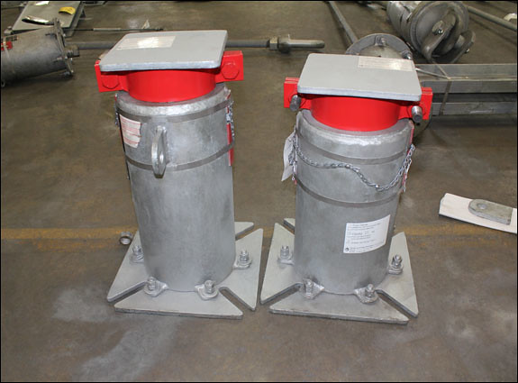
These variable spring supports were designed with an internal guide and engineered to accommodate 0.09 inches of vertical movement. The units were specified for a 5,350 lb. cold load and a 5,450 lb. hot load, ensuring proper load support throughout operating conditions.
A key design challenge for this project involved the required hydro-test load. The supports needed to withstand a hydro-test load exceeding 33,000 lbs, which significantly surpassed the standard maximum hydro-test capacity of approximately 18,000 lbs.
To address this requirement, PT&P incorporated special collars in conjunction with the standard travel stops. These collars were specifically engineered to absorb the extreme hydro-test loads by utilizing the high-strength characteristics of the load flange and housing assembly, while effectively bypassing the threaded internal components of the spring support.
This custom solution provided the strength and reliability required for the application while maintaining the operational functionality of the variable spring assembly.
Piping Technology & Products Leadership Appointed to Key MSS Technical Committees
Piping Technology & Products (PT&P), a global leader in engineered pipe support solutions, proudly announces that several senior executives have been appointed to serve on technical committees within the Manufacturers Standardization Society (MSS), one of the most respected standards organizations in the piping industry.
The appointments reinforce PT&P’s ongoing commitment to engineering excellence, safety, and the advancement of piping system standards across critical infrastructure industries worldwide.
PT&P Leadership Selected for MSS Committees
The following PT&P leaders have been appointed to participate in MSS technical committees:
Dr. Durga D. Agrawal, Ph.D., P.E. – Chairman & Founder
Rakesh Agrawal – CEO
Lloyd Kirchner – President & COO
Randy Bailey – Senior Vice President
Anu Agrawal-Lal – Vice President, Sales & Marketing
David Smith – Director of Engineering & Projects
The team will contribute their expertise to:
MSS Committee 403 – Pipe Hangers and Supports
MSS Committee 111 – Product Regulation, Certification, and Industrial Policies
These committees play a critical role in developing and maintaining standards used throughout the power generation, LNG, petrochemical, semiconductor, pharmaceutical, and industrial sectors.
Supporting Industry Standards Through Engineering Expertise
For decades, PT&P has specialized in solving complex piping engineering challenges involving high loads, thermal movement, vibration control, and space-constrained installations. Participation in MSS technical committees allows the company to contribute real-world engineering experience directly into the standards that guide critical piping infrastructure projects globally.
MSS standards are widely referenced within ASME piping codes, including:
ASME B31.1 – Power Piping
ASME B31.3 – Process Piping
ASME B31.9 – Building Services Piping
By participating in the standards development process, PT&P helps ensure that piping systems continue to meet evolving demands for safety, reliability, and operational efficiency.
Advancing Safety and Innovation in Critical Infrastructure
As industries such as LNG, data centers, semiconductor manufacturing, and pharmaceuticals continue to expand, the need for high-integrity pipe support systems has become increasingly important. PT&P’s involvement with MSS demonstrates its dedication to advancing engineering best practices that support these mission-critical facilities.
According to David Smith, Director of Engineering & Projects at PT&P:
“Standardization is the bedrock of safety and innovation in our industry.”
PT&P’s engineering and manufacturing teams bring decades of experience in:
Spring hangers and supports
Pipe shoes and guides
Expansion joints
Pre-insulated pipe supports
Pipe stress analysis
Shock and vibration control solutions
A Commitment to Quality and Manufacturing Excellence
PT&P’s contributions to MSS are backed by advanced manufacturing capabilities and rigorous quality assurance processes. The company utilizes modern production technologies, computer-controlled manufacturing systems, and comprehensive load testing procedures to ensure precision and reliability across all products.
Headquartered in Houston, Texas, PT&P serves customers worldwide with engineered pipe support and expansion joint solutions designed to reduce downtime, protect equipment, and improve long-term system performance.
About Piping Technology & Products
Founded in 1975, Piping Technology & Products is a leading manufacturer of engineered pipe supports, expansion joints, and custom piping solutions for industrial applications worldwide. PT&P supports projects across LNG, petrochemical, power generation, semiconductor, pharmaceutical, and heavy industrial markets with engineering-driven solutions focused on safety, reliability, and innovation.
Marinite® is widely used as an insulating material in hot piping support applications, with Grade P (Marinite-P) being the most commonly specified due to its excellent structural properties.
Marinite-P is well-suited for structural insulation thanks to its high dimensional stability, ensuring consistent performance under varying thermal and load conditions. It is incombustible, offers high thermal insulation values, and provides excellent compressive strength, making it ideal for high-load, high-temperature environments.
Additionally, Marinite® helps minimize decay, rust, and corrosion at the pipe support interface. Its durability allows it to withstand handling and installation conditions while providing long-term, reliable service. The material is also effective in fireproofing and heat-processing applications, with a maximum service temperature of up to 1200°F (649°C).
Major Advantages:
• High Compressive Strength.
Deflects less than 1/10 in. per inch of thickness under 4000 psi
Deflects less than 3/64 in. per inch of thickness under 2000 psi
• High Tensile strength.
• High resistance to shear and traverse forces.
Major Applications:
• Hot Line Pipe Supports in Power Generation and Process Industries
• Structural Insulation in Pipe
• Supports Backup Insulation in Rotary Kilns of Lime and Cement Plants.
• Ceramics and Foundry applications.
Coefficient of Friction:
0.08 @ minimum pressure
0.06 @ maximum pressure
Custom Big Ton Springs Designed for a 122,000 lb. Load for a Chemical Plant
Type:
Big Ton Spring Supports
Size:
52-3/4″ L x 38-3/4″ W x 91″ H
Design:
121,916 lb. Load | 3/4″ Upwards Movement
Material:
HDG Carbon Steel | Neoprene Coated Springs
Testing:
Load Calibration Test | Hydro-tested
Piping Technology & Products (PT&P) custom-designed abig ton spring support for a chemical plant in Pennsylvania to support a vessel with a load exceeding 121,916 lbs and accommodating 3/4 inch of upward movement.
The unit measures 52-3/4″ L x 38-3/4″ W x 91″ H and was engineered to handle substantial loads while allowing controlled movement within a confined space. Big Ton spring supports are specifically designed for heavy-duty applications, including vessels, compressors, and pumps in power and petrochemical facilities.
By incorporating a compact, high-capacity support solution, PT&P helped the client avoid a costly redesign of the piping system, delivering both engineering efficiency and cost savings.
This unit features an internal guide and a specially designed pedestal to meet the required elevation and withstand hydro-test loading conditions. A load calibration test was conducted prior to shipment to ensure performance and accuracy.
This project demonstrates PT&P’s ability to provide custom-engineered solutions for extreme load conditions, combining reliability, precision, and cost-effective design.
Piping Technology & Product’s marinite® slide bearing plates are engineered as rectangular assemblies designed for reliable load support and thermal movement accommodation.
Each assembly consists of a Marinite® insulating block sandwiched between stainless steel top and bottom plates, providing both structural integrity and thermal isolation. The components are securely held together by stainless steel side plates along the length and width, forming a durable and stable unit.
This design ensures consistent performance in applications requiring low-friction movement, load distribution, and protection against heat transfer, making Marinite® slide bearing plates a dependable solution for high-temperature piping systems.
Marinite® Plates Construction
The side and end plates have 1/4″ diameter through holes to better dissipate heat and are stitch-welded to the top and bottom plates. The bottom plate is polished to have a mirror finish and is mated with a sliding surface of polytetrafluoroethylene (PTFE) slide plate to provide a minimal coefficient of friction. The assembly is generally welded to shoes.
Marinite® Plates Application
The Marinite® insulator assemblyenables the use of polytetrafluoroethylene (PTFE) as a sliding surface in applications involving high operating temperatures and dynamic loading. It acts as a thermal barrier, protecting the PTFE from excessive heat transfer. This solution has been successfully used in power plants and other high-energy systems (SHP), where both thermal resistance and low-friction performance are critical. It could potentially be used wherever there are movements at top, bottom or laterally at the point support.
So the benefits of having a Marinite® insulator include:
Facilitates use of polytetrafluoroethylene (PTFE) on high-temperature lines.
Marinite being a high load bearing insulation material is ideal for the dynamic conditions.
Marinite® Plates: PT&P’s Capabilities
Piping Technology & Products is a leading supplier of Marinite® slide bearing plates, which—through proven testing—enable the use of polytetrafluoroethylene (PTFE) as the sliding surface, even in applications with extremely high operating temperatures.
These assemblies have been successfully supplied to numerous companies across the oil, gas, and power industries, demonstrating reliable performance in demanding environments.
How Piping Technology Cut Material Costs and Lead Times for $40+ Billion Semiconductor Plant
Background
A leading semiconductor manufacturer undertook the construction of a $40+ billion advanced fabrication facility, requiring extensive large-bore piping systems ranging from NPS 20” to 64”. Early in the project lifecycle, pipe support design and procurement quickly emerged as a critical path constraint, threatening both schedule and cost performance.
Piping Technology & Products (PT&P) was engaged to provide integrated engineering support, including pipe stress analysis, support redesign, and constructability improvements. The objective was clear: streamline execution, reduce costs, and accelerate delivery timelines while ensuring full compliance with ASME code requirements.
The Challenge
The project faced several compounding challenges that stalled progress:
Overspecified Support Designs Pipe supports were engineered far above actual operating loads (3–60 kips), increasing steel usage, fabrication complexity, and field welding requirements.
Incomplete and Inconsistent Design Inputs Missing node data, incomplete models, and conflicting drawings created uncertainty, preventing confident support selection and procurement.
Dependency on Pipe Stress Validation Without validated stress analysis, support loads and configurations could not be finalized, creating a bottleneck across multiple systems.
Extended Lead Times Impacting Construction Procurement lead times of 14–20 weeks combined with unresolved engineering issues posed a direct risk to installation sequencing and project completion.
The Solution
PT&P implemented a comprehensive engineering and field support strategy to overcome these challenges and restore project momentum.
Reverse Engineering & Pipe Stress Analysis:
With incomplete inputs, PT&P reconstructed piping system models to establish a reliable design basis:
Extracted geometry directly from the client’s Revit BIM model
Reconciled discrepancies between isometric and mechanical drawings
Developed CAESAR II models for ASME-compliant pipe stress analysis
Established accurate loads, displacements, and support reactions
This process eliminated design ambiguity and enabled informed decision-making.
Load-Based Support Redesign:
Using validated stress data, PT&P transitioned from conservative assumptions to load-driven design:
Replaced overdesigned welded supports with clamp-on pipe shoes
Sized supports based on actual operating loads
Reduced field welding and hot work by approximately 90%
Lowered material usage and fabrication complexity
This redesign directly addressed unnecessary cost drivers and improved efficiency.
PT&P reverse-engineered piping systems and performed CAESAR II pipe stress analysis to validate support loads and optimize support configurations for large-bore piping systems.
Design Optimization & Constructability:
To ensure a buildable and efficient solution:
Optimized support geometry for tight pipe rack constraints
Standardized designs to improve manufacturability
Integrated neoprene isolation to mitigate vibration and pipe interaction
Delivered fully validated, stress-backed support configurations
These improvements enhanced constructability and enabled smoother installation execution.
Field Execution & Engineering Support:
PT&P engineers provided field verification and installation support to ensure support designs were implemented in accordance with project requirements and design intent.
PT&P extended support beyond design into active field involvement:
Conducted daily walkdowns to verify installation and fit-up
Identified and resolved misalignment issues early
Ensured installation aligned with engineering intent
Accelerated approval and system handover processes
This hands-on approach minimized rework and kept the project on track.
Results
The integrated engineering and field strategy delivered measurable improvements:
Reduced procurement lead times from 14–20 weeks to approximately 6 weeks
Lowered material costs by eliminating overspecification and excess steel
Improved constructability by minimizing field welding and simplifying installation
Accelerated project schedule and enabled on-time commissioning
Unblocked engineering progress through validated stress analysis and model reconstruction
Permali® and Insulam® are high-performance insulating materials designed for applications requiring high tensile and compressive strength (see table below). Due to their exceptional resistance to moisture, these materials are particularly well-suited for use in pipe support applications—such as flare lines and dummy legs—where exposure to harsh environmental conditions is common.
Permali® and Insulam® are phenolic laminated products (densified, resin-impregnated wood) manufactured from carefully selected thin beechwood veneers. These veneers are impregnated under vacuum conditions with a specialized synthetic resin and then densified through the application of heat and pressure.
The result is a homogeneous material that combines the inherent strength and toughness of natural wood fibers with the enhanced stability, durability, and dielectric properties of advanced thermosetting resins.
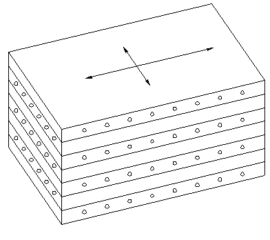
The laminated block material is produced with cross-directional fiber orientation, as illustrated in Figure 10 below, providing uniform strength and improved performance in multiple loading directions.
NOTE: Cross-laminated.
For components in compression or for parts stressed in more than one direction.
Sizes to suit most applications.
Density
Permali
Compressive Strength
30,000.00
Flexural Strength (flatwise with grain) (psi)
15,000.00
Tensile Strength (with grain) (psi)
15,000.00
Modulus of Elasticity (psi)
2.0 x 10^6
Closed Cell Content (%)
N/A
Temperature(F)-Continuous Operation
221.00
K-Factor
N/A
Thermal Conductivity (btu/hr m^2 of)
0.0018
Shear (flatwise) (1/8″ thick) (psi)
7200.00
Density (lb/in^3)
0.0469
Water Absorption (%)
0.75
Pig Launchers and Receivers Custom Designed for a Chemical Plant
Type:
Pig Launchers & Receivers
Size:
4-14” Diameter | 72-98″ Long | 48″ Tall Stands
Material:
316 L SS | SA 106-B | SA-105
Design:
Operating Temperature: 221°F
Operating Pressure of 117, up to 205 PSI
PT&P’s Sweco Fab division custom designed and manufactured pig launchers and receivers for a chemical plant in Saudi Arabia, delivering a reliable solution for pipeline maintenance and operational efficiency. A pig launcher is a pressurized vessel used to introduce a cleaning or inspection device (“pig”) into a pipeline. These systems enable a variety of functions, including cleaning, inspection, and maintenance, without interrupting pipeline operations. Pig launchers and receivers are widely used across industries such as oil and gas, chemical processing, food production, paint manufacturing, and cross-country pipelines.
The primary advantage of pipeline pigging systems is the ability to maintain and inspect pipelines without shutting down flow, reducing downtime and preventing cross-contamination—resulting in significant cost and time savings for plant operations and maintenance teams.
These units were fabricated using 316L stainless steel, SA-106 Grade B, and SA-105 materials, ensuring durability and corrosion resistance in demanding environments. The pig launchers and receivers were produced in sizes ranging from 4″ to 14″ in diameter, with lengths between 72″ and 98″, and were mounted on 48-inch-tall support stands.
The assemblies were designed for an operating temperature of 221°F and pressures ranging from 117 to 205 PSI, meeting the performance requirements of the application.
This project highlights PT&P’s capability to deliver custom-engineered pipeline solutions that enhance system reliability, reduce maintenance downtime, and support efficient plant operations.
Heavy Duty Yoke U-Bolt Pipe Clamps Designed for a Pipeline in Canada
Piping Technology & Products designed and manufactured custom Fig. 43 yoke u-bolt pipe clamps for a pipeline in Canada. Engineered for 42-inch diameter pipe, these clamps were fabricated from hot-dip galvanized carbon steel to ensure durability and corrosion resistance in demanding environmental conditions. Each assembly was designed to support loads of up to 27,500 lbs, providing reliable structural support for critical piping systems.
PT&P supplied a total of 28 assemblies within a three-week timeframe, meeting the project’s expedited schedule without compromising quality.
Prior to manufacturing and shipment, our engineering designed these clamps utilizing Finite Element Analysis (FEA). Through FEA, PT&P engineers were able to simulate real-world loading conditions, ensuring the design could withstand extreme stresses while minimizing the risk of failure in service.
This project highlights PT&P’s ability to deliver high-strength, custom-engineered pipe support solutions backed by advanced analysis and rigorous quality control.
PT&P REF. ORIGINAL POST 01242015
Improve Piping System Reliability with Anchors, Guides and Slides in Cooling Systems
How to Build a Reliable Cooling System with Proper Pipe Supports
A cooling system consists of pipes, slides, guides, and anchors that provide a carefully engineered framework for safely managing pressure, temperature, and flow. These components work together to handle thermal expansion, maintain the integrity of the entire network, and ensure minimal energy loss.
How Pipe Guides Prevent Failure
Pipe guides play a critical role in directing thermal expansion. They ensure that movement travels straight into the expansion joints rather than shifting off-axis. Without this precise direction, pressurized chilled water lines can experience sudden failures. Using the right guides helps maintain the facility’s safety by keeping forces contained within their intended path.
How to Improve Performance with Low-Friction Slide Plates
To further protect the system, engineers often integrate slide plates lined with PTFE. These plates allow chilled water pipes to move smoothly with very little friction. This setup reduces the overall wear and tear on the piping and supports. When movement is fluid and unrestricted, the system lasts longer and requires less frequent maintenance, saving the operator time and costs.
Pipe anchors are used to isolate the piping system from the process equipment and prevent end forces from system expansion and contraction from being transferred to sensitive process equipment that isn’t designed to carry them.
Secure Your Piping System with Anchors, Guides, and Slides
Contact our engineering team today to discuss custom supports and 3D design verification for your next project.
Frequently Asked Questions: Pipe Anchors, Guides, and PTFE Slides
What are the main benefits of using pipe guides in cooling systems?
Pipe guides prevent catastrophic failures by directing thermal expansion into expansion joints. This keeps movement aligned and protects pressurized lines from shifting in dangerous directions.
How do PTFE slide plates help industrial piping?
PTFE-lined slide plates provide a low-friction surface, allowing pipes to move easily as they expand or contract. This reduces physical stress and wear on the cooling system components.
What is design verification for pipe supports?
Design verification involves using 3D modeling and 3D printing to test specialty pipe supports before they are manufactured. This helps clients confirm that the supports will work correctly in complex cooling systems.
Can I get custom designs for my facility’s piping framework?
Yes, PT&P offers custom design capabilities to create supports, anchors, and guides tailored to specific cooling system requirements. This ensures the system has the exact flexibility and strength it needs to run safely.